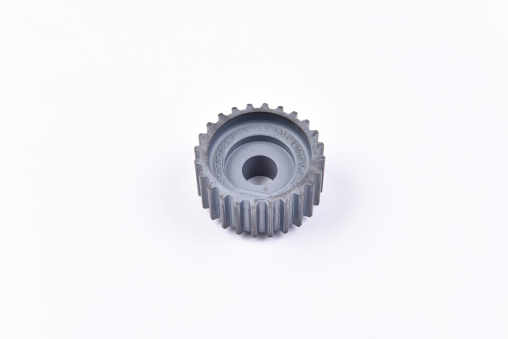
Powder Metallurgy Wall Thickness: Minimum Numbers, the Length-to-Wall Rule, and DFM Checklist
A working guide to PM wall thickness, from the MPIF Standard 35 minimum through the 8:1 length-to-wall rule and the 3:1 section ratio. With the numbers we actually hold on our press shop floor, the parts we have learned to redesign, and a DFM checklist that catches the most expensive drawing mistakes before you spend anything on tooling.

Key Takeaways
- Minimum wall thickness: 1.5 mm per MPIF Standard 35; 2.0 mm is the working minimum; 2.5 to 6.0 mm is the band where every part comes out uniformly dense. (Industry general-dimension tolerance sits at ±0.1 to 0.13 mm as-sintered; our controlled process holds ±0.05 mm on critical dimensions, then ±0.025 mm on selected critical dimensions after sizing or light CNC — numbers aligned with our PM tolerance guide.)
- Length-to-wall ratio: maximum 8:1 per MPIF Standard 35; keep it at or below 6:1 in practice so density holds from end to end. The 6:1 ceiling is a roughly 25% safety margin against the published 8:1 maximum.
- Section ratio (thick-to-thin): maximum 3:1; beyond that, the thin section under-densifies and the part cracks at the transition.
- Transitions and corners: gradual, with fillet radius at least 0.5 mm and 1.0 to 2.0 mm preferred. Sharp internal corners are stress concentrators and tool-wear sites.
- What we hold on the floor: 19 PM presses, 10 sintering furnaces, 2 continuous lines, and free 48-hour DFM review on every drawing — so the wall thickness callout matches the part before tooling is ordered.
The Bracket That Cracked at 0.8 mm
A buyer sent us a sensor bracket last year, drawn with a 0.8 mm wall along a 25 mm length. The drawing was clean. The part was going into a small electric motor housing and the engineer wanted a thin wall to save weight. We quoted it. The DFM review caught it before tooling: the length-to-wall ratio was over 30:1, the wall was below the MPIF 35 minimum, and the section next to it was 4.5 mm thick, which made the section ratio almost 6:1. The press would have under-filled the wall, the sintering furnace would have warped it, and the part would have cracked at the 0.8 mm to 4.5 mm transition under static load. In service, the same failure mode would have been a slow one: micro-leakage past the housing seal face and bearing bore wear as the loose powder at the thin edge abraded the mating surface over thousands of cycles — the kind of wear a sintered part is supposed to prevent, not cause.
It was not a hostile drawing. The engineer had been told the part was going to be “die cast or sintered,” picked sintered, and never worked through what the press can actually fill. The minimum wall in his CAD was set by the wall-thickness tool in his modelling software, not by the press shop floor. The part as drawn was not a sintered part; it was a die cast part being asked of a press.
Two changes fixed it. We moved the wall to 1.8 mm and shortened the unsupported length to 12 mm. The length-to-wall ratio dropped to 6.7:1, well inside the working band, and the section ratio against the 4.5 mm boss came down to 2.5:1, well under the 3:1 ceiling. The buyer got the lighter part he wanted, the part came out uniformly dense, and the tooling went in on the first attempt. That is the lesson: wall thickness on a sintered part is decided by what the press can fill, not by what a CAD tool suggests.
The rest of this article is the working out of that lesson, with the numbers we hold on the press shop floor and the rules that decide them.
Why Wall Thickness Is the First DFM Call You Make
Every other PM design rule answers to wall thickness. Tolerances are set by which features are on a thin wall versus a thick wall. Surface finish is set by whether the wall was sized, machined, or left as-sintered. Cost is set by how many secondary operations the wall forces. If the wall thickness is wrong, nothing else on the drawing can save the part.
This is different from machined parts, where wall thickness is mostly a stiffness and weight consideration. On a sintered part, wall thickness is a process consideration. The press needs enough powder mass to fill the cavity, the punches need to deliver enough force to compact that powder to target density, the furnace needs enough thermal mass to sinter it uniformly, and the part needs to come out of the die without cracking on ejection. Get the wall thickness wrong and the rest of the process degrades with it.
Three numbers matter, in this order of importance: the minimum wall thickness, the length-to-wall ratio, and the section ratio (thick-to-thin). The minimum wall is the floor. The length-to-wall ratio is the structural limit on a single wall. The section ratio is the limit on adjacent walls of different thickness. We will go through each.
Industry Minimum Wall Thickness: 1.5 mm, But Plan for 2.0 mm
The widely cited industry minimum is 1.5 mm (0.060 inch). It comes from MPIF Standard 35, the materials standard that has guided PM design for decades, and it is the floor you can hit on small iron-base parts with controlled powder fill. On a small sensor flange, a 1.5 mm wall will compact and sinter cleanly. On a larger structural part, a 1.5 mm wall will probably under-fill and warp.
In practice we work to a different number. We aim for 2.0 mm as the working minimum on iron-base parts, and 2.5 mm on stainless and aluminum parts where the powder is harder to compact. Below 2.0 mm, the wall starts to inherit fill variation, the part starts to inherit density variation, and the dimensional scatter after sintering starts to eat the tolerance band the rest of the drawing assumed.
The optimal band is 2.5 to 6.0 mm. In that range, the powder fills the die cavity evenly, the punch delivers consistent pressure through the section, and the sintering furnace brings the wall up to uniform density. Above 6.0 mm, the wall is still good but you are using more material than you need. Above 10.0 mm, the wall needs attention because the centre of the section starts to under-compact.
| Wall thickness | What to expect | When to use it |
|---|---|---|
| 1.5 mm | Industry minimum (MPIF 35). Density variation is visible at the edges. | Small iron-base parts, controlled fill, no heavy load. |
| 2.0 mm | Working minimum. Density is acceptable across the wall. | Most structural PM parts. Our default floor. |
| 2.5 to 6.0 mm | Optimal band. Uniform density, low scrap, predictable shrinkage. | Most production PM parts. The band we design for. |
| 6.0 to 15.0 mm | Acceptable. Centre of the section starts to under-compact above 10 mm. | Structural sections, hubs, flanges. Re-press if needed. |
| 15.0 to 25.0 mm | Heavy. Needs re-press, warm compaction, or powder forging. | High-load structural parts. Confirm with your supplier. |
| Above 25.0 mm | Above the practical ceiling for press-and-sinter. | Re-route to casting, forging, or powder forging. |
General-dimension wall thickness tolerance is roughly ±0.1 to 0.13 mm as-sintered for an industry-typical process; our controlled process holds ±0.05 mm on critical dimensions and ±0.025 mm on selected critical dimensions after sizing or light CNC. The same wall can come off two different presses at two different tolerances; the part number is not the whole story.
Length-to-Wall Ratio: The 8:1 Rule and Why We Use 6:1 in Practice
The second number is the length-to-wall ratio. MPIF Standard 35 sets the maximum at 8:1. In our shop we work to 6:1 as a soft ceiling on the same iron-base materials, and to 4:1 on stainless and aluminum where the powder is less free-flowing.
The reason is the same as for wall thickness, but with one more step in the chain. Pressure from the punch decays with distance through the powder. On a long thin wall, the end of the wall nearest the punch sees full compaction pressure; the far end sees a fraction of it. The part comes out of the press with a density gradient from end to end. After sintering, that gradient becomes dimensional scatter, and the scatter is not predictable across production lots because the powder fill varies from shot to shot.
The fix is not to add a secondary operation. The fix is to redesign the part so the section is shorter or the wall is thicker. A boss added at the unsupported end of the wall splits the length into two shorter sections, both inside the 6:1 band. A wall thickness increase from 1.8 to 2.5 mm drops the ratio from 13.9:1 to 10:1, which still needs a redesign, but at 3.0 mm it drops to 8.3:1, and at 3.5 mm to 7.1:1, inside the working band.
| Material | MPIF Standard 35 ceiling | Our working ceiling |
|---|---|---|
| Iron-base (Fe, Fe-Cu, Fe-Ni) | 8:1 | 6:1 |
| Stainless steel (304, 316L, 17-4PH) | 8:1 | 4:1 |
| Aluminum (Al-Si, Al-Cu) | 8:1 | 4:1 |
| Soft magnetic (Fe-Si, Fe-P) | 8:1 | 6:1 |
Section Thickness Ratio: The 3:1 Rule Between Adjacent Walls
The third number is the section ratio between adjacent walls of different thickness. The maximum is 3:1. Beyond that, the thin section under-densifies because the punch force flows preferentially into the thick section, and the part cracks at the transition between sections during ejection or sintering.
This rule catches a lot of drawings. A housing with a 2.5 mm wall and a 12 mm hub boss has a section ratio of 4.8:1, well over the 3:1 ceiling. The part will either come out of the press with a low-density hub, or it will crack at the junction between the wall and the boss during ejection, or both. Either way, the scrap rate on the production line goes up.
Two redesigns work. The first is to drop the boss height so the section ratio comes under 3:1. A 2.5 mm wall with a 7 mm boss is 2.8:1, inside the working band. The second is to add a gradual transition between the wall and the boss, with a fillet radius of at least 1.0 mm. The fillet gives the punch force a path to flow evenly into both sections, and gives the sintering shrinkage a path to release without cracking.
MPIF Part Classes: Where the Thickness Rules Show Up
MPIF Standard 35 sorts PM parts into four classes by geometry, and each class inherits the wall thickness rules above. Knowing the class is the quickest way to talk to a PM supplier about a part, because the class tells them what tooling they are looking at.
- Class I — single-level thin parts. One level of thickness, typically under 5 mm wall. The simplest tooling: one upper punch, one lower punch, one core rod. Most gears, spacers, and simple structural discs land here.
- Class II — single-level thick parts. One level of thickness, over 5 mm wall. Same tooling as Class I, but the press capacity matters. Above 20 mm wall, the centre of the section starts to under-compact and a re-press is needed.
- Class III — two-level parts. Two distinct thickness levels in the same part, like a flange with a hub. Needs stepped upper or lower punches, or a shelf die. The 3:1 section ratio rule applies directly here.
- Class IV — multi-level parts. Three or more thickness levels. Needs multiple upper and lower punches, shelf core rods, or a shelf die. The most expensive tooling class and the most sensitive to the section ratio rule. Above four levels, the cost of the tooling starts to outweigh the cost of the secondary operations it would replace.
If you are sketching a part and you are not sure which class it lands in, count the distinct thickness levels in the cross-section. One level means Class I or II. Two levels means Class III. Three or more means Class IV, and that is the part to put in front of a PM supplier before you commit to tooling.
PM Wall Thickness DFM Checklist
Most wall thickness mistakes on PM drawings are caught by the same six questions. Run every drawing through this list before tooling is ordered.
- Is the minimum wall above 2.0 mm? Anything below 2.0 mm needs a justification. The justification usually has to be that the part is small (under 25 mm in its longest dimension) and the powder is iron-base. If the part is large or the material is stainless or aluminum, the working minimum is 2.5 mm.
- Is the length-to-wall ratio at or below 6:1? For iron-base, the working ceiling is 6:1. For stainless and aluminum, 4:1. Above the ceiling, redesign the part by adding a supporting boss, shortening the unsupported length, or thickening the wall.
- Is the section ratio (thick-to-thin) at or below 3:1? The thickest section in the part divided by the thinnest section should be 3:1 or less. Above 3:1, the thin section under-densifies or the part cracks at the transition. The fix is a boss height change or a fillet, not a secondary operation.
- Are the internal corners filleted, not sharp? Minimum fillet radius 0.5 mm. Preferred 1.0 to 2.0 mm. Sharp internal corners are stress concentrators and tool-wear sites. A chamfer at 30 to 45 degrees with a 0.13 mm flat is acceptable where a fillet is not.
- Are the section transitions gradual? Any change in wall thickness should happen over a distance of at least one wall thickness, not as a step. A 2.5 mm wall going to a 6 mm boss should ramp over at least 2.5 mm, ideally 5 mm, with a fillet at the transition.
- Is the heaviest section under 25 mm? Above 25 mm, the centre of the section will under-compact on a single press. Either re-route the part to keep the heavy section under 25 mm, plan for a re-press, or re-route the part to a different process (powder forging, casting, or MIM).
Apply the Rule by Feature: Where Wall Thickness Matters Most
Different features on the same part have different wall thickness requirements. The rule of thumb: thicker for structural sections, thinner only where the part geometry forces it. Here is the working list.
| Feature | Minimum wall | Why |
|---|---|---|
| Structural wall (housing, bracket) | 2.0 mm | Carries load across a span. Thin walls flex and crack at fasteners. |
| Hub (gear, sprocket, cam) | 2.0 mm | Transmits torque to the shaft. Thin hubs shear under cyclic load. |
| Flange | 2.5 mm | Carries the part on a mating face. Thin flanges warp in sintering. |
| Gear tooth (root) | 1.2 mm | The thinnest point in a gear. Below 1.2 mm the tooth cracks during ejection. |
| Rib or fin | 1.5 mm | Stiffening features. Below 1.5 mm the rib does not stiffen. |
| Boss (mounting, fastener) | 2.0 mm wall, 15 percent of height max | Bosses are pockets in the punch. Above 15 percent of part height, the boss sticks in the punch on ejection. |
| Web between hub and OD | 1.5 mm | Carries the part from hub to flange. Below 1.5 mm the web tears during ejection. |
What We Hold on Our Floor
Since this article is on our site, our own numbers, with what is behind them:
- Working minimum wall: 2.0 mm iron-base; 2.5 mm stainless and aluminum. Below 1.5 mm (MPIF Standard 35 minimum) we ask for a written justification before tooling is quoted.
- Length-to-wall ratio ceiling: 6:1 iron-base; 4:1 stainless and aluminum. MPIF Standard 35 (Structural Parts standard, first published in 1998 by the Metal Powder Industries Federation, applicable to conventional press-and-sinter ferrous and non-ferrous parts) sets 8:1 as the published maximum; we work to a tighter ceiling so density holds from end to end across a production run.
- Section ratio ceiling: 3:1 between any two adjacent walls. Above that, the thin section under-densifies or the part cracks at the transition. The fix is a fillet radius, not a secondary operation.
- Internal corner fillet: R 0.5 mm minimum, R 1.0 to 2.0 mm preferred. Chamfer at 30 to 45 degrees with a 0.13 mm flat is acceptable where a fillet is not feasible.
- 19 PM compaction presses from 6 to 1,000 tonnes, with fill control and SPC running on critical dimensions — so the wall thickness on every part is what the drawing called out, not what the press happened to fill that day.
- 10 controlled-atmosphere sintering furnaces, including 2 continuous high-volume lines. The shrinkage data per material is what makes a 2.0 mm wall hold a 0.05 mm tolerance repeatably, and we have that data for the materials we run regularly.
- Zeiss CMM inspection, gear profile tester, and density testing on every PM lot. Capability studies (Cpk) on critical dimensions, under IATF 16949:2016 — PPAP and MES batch traceability, so the numbers follow every lot.
When a drawing comes in, our DFM review marks every wall thickness against the three rules above — before you have spent anything on tooling. That review is free, and it comes back within 48 hours.
FAQ: PM Wall Thickness
What is the minimum wall thickness for powder metallurgy?
What is the length to wall thickness ratio for PM parts?
Can you do thin walls with powder metallurgy?
Why does wall thickness affect density in PM parts?
What is the maximum wall thickness for a PM part?
Send Us the Drawing. We Will Mark Which Wall Callouts to Keep, Drop, or Change.
Not sure whether your drawing’s wall thickness callouts fit the PM process? Send it to engineers who hold these numbers in production, not on a datasheet.
Attach your drawing and note the structural sections, hubs, and bosses. We will mark which wall callouts to keep, drop, or change against the MPIF 35 minimum, the 6:1 length-to-wall ceiling, and the 3:1 section ratio — with cost delta for each — and route the part to the right press. Tolerance and finish review come back together, within 48 hours.
Send Your Drawing for a Free Wall + Tolerance + Finish Review