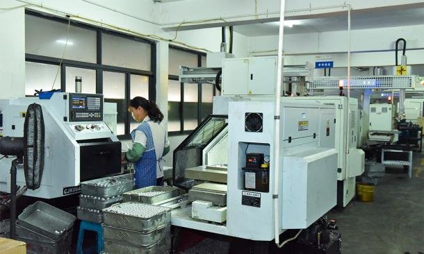
How Are “Sintered Molds” Made? The Compaction Dies That Press Sintered Parts
A direct look at the tooling behind powder-metallurgy parts – what a “sintered-parts mold” actually is, the steel it is cut from, the in-house route that builds it, and where the tolerance really comes from. For engineers and buyers who have seen the part but never opened the tool.
First, the words: a PM die and a sintered part are different things
Most of the confusion in the phrase “sintered mold” collapses once you separate two objects that share the same shape but not the same history.
- The die (mold / tooling) is the hardened steel cavity that shapes the powder under pressure. It never goes in the furnace, and it is never made by sintering.
- The part is the green compact that die presses, which then does go through a sintering furnace where the metal powder bonds into a solid. That is the step the “sintered” label refers to.
So when someone asks “how are sintered molds made,” there are two honest readings, and both are useful. Either they mean how the part tooling is built (this page), or they are using “mold” loosely for the process that shapes a sintered part. The full powder-to-part sequence is covered across our wall-thickness and structural-parts pages; this one stays on the tooling, because a good die is what makes production economics and repeatable tolerance possible in the first place.
A compaction die set is several jobs wearing one tool
Open up a PM tool and you will not find a single block. You find a set of parts that each move separately during the press stroke:
| Component | What it does | Typical material / build | Why it matters |
|---|---|---|---|
| Die body (cavity) | Contains the powder and defines the outer part shape | Hardened tool steel; carbide insert for tight or high-wear profiles | If the bore runs out of round, every part is out of round |
| Upper punch | Pushes down from the top, defines the upper form and flat | Hardened tool steel, ground | Carries the compaction load; sets the top detail |
| Lower punch / punches | Support the powder, move up to eject, and form steps and bosses from below | Hardened tool steel, stepped for multi-level parts | How the part gets its internal levels and how it is pushed out |
| Mandrel (core rod) | Forms the through-hole in bushings and gears | Hardened tool steel or carbide, EDM-finished OD | Hole position and roundness come from this rod |
| Sizing tool (separate) | Re-presses the sintered part to tighten dimensions and flatness | Hardened tool-steel die and mandrel | Brings tight features into about ±0.025 mm after sintering |
| Retractable-tooth segments | Form internal teeth, withdraw after the stroke for ejection | Carbide or tool-steel segments on a cam and die set | The clean way to make PM ring gears and internal splines |
The number of punches is what makes tooling expensive. A simple flat bushing is two punches and a mandrel. A two-level gear is four to six. A complex structural part with several height levels can carry six or more moving elements, each with its own taper, clearance, and heat-treat requirement. That is why a single PM program’s tooling cost has to be weighed against the scrap it prevents, not the steel it contains.
Die material: steel for the body, carbide where the wear is
There is no single “PM die steel.” The grade is chosen against three variables: how many parts the tool must survive, how abrasive the powder is (iron and iron-copper powders are mild; others bite harder), and how tight the geometry is. The table below is a working reference, not a JH specification; the exact grade for your part is settled in DFM:
| Duty | Common material class | Why it is used | Limiting consideration |
|---|---|---|---|
| Low-to-moderate volume | Cold-work tool steel (A2 or D2-class air- or oil-hardening) | Good wear life, dimensional stability after heat treatment, cost-effective to machine | Wear life is finite; not for very long or highly abrasive runs |
| High volume / tight profile | Carbide insert at the cavity or core-rod surface | Carbide resists abrasive wear far longer than tool steel on teeth and bores | Carbide is brittle and costly to finish; applied where the geometry and volume justify it |
| Through-hardened punches | Tool steel hardened to service hardness, then ground | Punches take repeated impact and must not mushroom | Too hard is brittle; too soft means the punch face wears and density drifts |
| First-article / short pilot | Machinable pre-hardened steel, heat-treated after try-out | Cheap to iterate before production tooling is cut | Pilot tooling does not carry full production tonnage |
Material rows above are Industry Reference guidance (Category A), not a supplier promise – shrinkage, powder grade, volume, and geometry all shift the choice. Treat the row that fits your part as a starting point for the DFM discussion, not a finished spec.
The in-house build route, step by step
Because JH PM builds tooling in-house, the design and the manufacturing sit under one roof – which is exactly where a dimension error gets caught before steel is cut. The route looks like this:
- Design with partition and shrinkage in view. Engineers split the part into pressable levels, add draft and radii where ejection needs them, and scale the cavity up by the expected sintering shrinkage (roughly 0.2-0.5% for iron-base material) so the finished part lands on nominal. Design that skips this step cuts a die that makes parts nobody can use.
- Cut the steel. CNC milling and turning rough the die body and punches from tool steel stock. Long internal features are opened with wire EDM.
- Finish the cavity by EDM. Wire or sinker EDM finalizes the tooth forms, bores, and pockets to the drawing tolerance. Where the profile is tight or the run is long, a carbide insert is EDM-finished and set in.
- Heat-treat and grind. The die body and punches are hardened for wear life, then ground on the OD, bore, and faces so the moving parts run true. Grinding after hardening is what keeps a punch from binding or a bore from drifting oval.
- Try out, press, and prove it. The set goes into the press, green compacts are pressed, and a sintered sample is measured on a Zeiss CMM against the drawing. Tooling typically lands in about 20 working days for a conventional single-level set; multi-level and retractable-tooth gear tooling runs longer. First-article samples follow about 25 days after tooling release, each with its dimensional report.
This is the same wall-thickness and section-ratio discipline that governs pressing itself, just applied one step earlier – because a tool drawn past what the press can fill or the furnace can hold is a tool that makes scrap.
Where tolerance comes from: the die is drawn oversized on purpose
The single most misunderstood fact about PM tooling is the direction of the compensation. The part that looks like your drawing inside the die is actually the drawing scaled up.
Sintering shrinks the pressed part. For a typical iron-base structural material the linear shrinkage is roughly 0.2-0.5% – an Industry Reference range; the validated factor for your alloy and geometry comes out of the DFM note and gets confirmed on the first article. The die cavity is machined larger than the finished print by that expected amount. Get the compensation right and the part lands on nominal straight out of the furnace. Get it wrong – or skip it because the geometry looks simple – and you spend the whole program fighting a dimension that no amount of post-processing will fully fix at volume.
That is also why the tolerances PM can hold are not a wish list. As-sintered critical features commonly hold around ±0.05 mm at JH PM, and a sizing tool re-presses selected dimensions to roughly ±0.025 mm – Supplier Capability figures, dependent on the die carrying the compensation correctly and on the press and tooling holding up their end of the contract.
From the tool room
A customer’s sleeve called for a ±0.03 mm bore. The easy read was that a tight bore is a machining problem. The actual fix was a carbide core rod EDM-finished to the compensated size, run through a sizing tool after sintering – no grinding line item, no clamp on the bore, just the right die geometry and the furnace doing its predictable shrink. The part shipped inside spec because the tool carried the tolerance.
Seven questions to ask whoever is building your PM die
Tooling is the most expensive single line item in a press-and-sinter program, and it is also where the quality is locked in. Ask these before you commit:
- Is the tooling built in-house or outsourced? An in-house tool room and the press line under one roof means the die is tried on the actual production press, not a copy.
- What shrinkage compensation are you designing for, and how was it validated? The answer should name a number for your material (iron-base roughly 0.2-0.5%) and a first-article CMM check that confirms it.
- Where does the wear go – steel or carbide? If your run is long or the profile is tight, the answer should involve carbide at the cavity or core rod, not bare tool steel that drifts after tens of thousands of strokes.
- How many punches does the tool have, and can it eject cleanly? Too few punches for a multi-level part means density gradients and ejection cracks.
- What does the first-article report actually contain? It should be a CMM dimensional report against the drawing, not a “looks good” picture.
- How is a worn tool serviced? Repairing a die is not the same as rebuilding it; know the turnaround before the press goes down.
- What happens if the sintered part misses? A supplier that treats the die and the furnace cycle as one system fixes the root cause; one that blames your drawing does not.
FAQ – Sintered-Parts Dies and PM Tooling
Before You Cut a Die, Let Engineering Look at the Tool.
Upload your drawing (STEP or PDF) with annual volume. Within 48 hours you get a written DFM note covering tool construction – die, punches, mandrel, and whether the profile needs carbide – plus shrinkage compensation for your material, the sizing route for tight features, and the tooling and per-piece cost of each option. Tooling is built in-house; first-article samples ship with a CMM report. IATF 16949, 19 compaction presses from 6 to 1,000 t, 10 sintering furnaces including 2 continuous lines, 3 Zeiss CMMs.