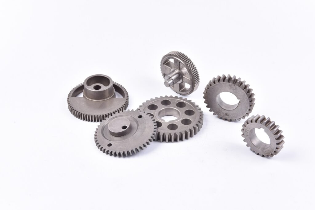
Custom Sintered Parts Manufacturer: Materials, Tolerances & Production
How technical procurement teams and mechanical engineers specify, tool, and qualify custom powder metallurgy components — with achievable tolerances, MPIF-aligned material grades, in-house tooling lead times, and auditable quality controls.
Custom sintered parts are near-net-shape powder metallurgy components engineered to proprietary customer drawings. Unlike catalog stock bushings, every feature — multi-level hubs, blind splines, involute gear teeth, oil-retention porosity — is tailored to your print: alloyed powder is blended to spec, compacted in dedicated carbide tooling, and sintered below the melting point to the required density and geometry.
- Material envelope: MPIF Standard 35 iron and copper steels, 316L / 17-4 PH stainless, self-lubricating bronze (150–850+ MPa tensile).
- Tolerances: ±0.05 mm as-sintered on die-formed radii; ±0.025 mm on critical bores after sizing.
- Facility: 19 automatic presses (6–1,000 t), 2 continuous sintering furnaces, 3 Zeiss CMMs.
- Commercial: MOQ 2,000 pcs; tooling 25 working days; T0 first articles 35 working days; DFM within 48 hours.
What Are Custom Sintered Parts?
In high-volume assemblies, catalog bushings and off-the-shelf gears force design compromises. Custom sintered parts reverse that constraint: with powder metallurgy the final geometry is pressed directly into a precision die cavity, so stepped flanges, blind keyways, involute teeth, cam tracks and irregular lugs form in a single 1–3 second press stroke at over 95% material utilization.
The trade-off is real and worth stating: every custom part needs its own die set, so PM only makes economic sense once a design is frozen and volume justifies tooling. If your project is still iterating weekly, machining prototypes first is the honest recommendation. When the drawing stabilizes, we quote the PM path.
Related: how to select the right PM material and the quality-control pillar cover the full decision chain.
The 4 Engineering Decisions Built into Every Custom Part
Specifying a custom sintered component means harmonizing four variables during the DFM phase. Each one changes tooling, cost, or both:
1. Compaction kinematics & pressing direction
Powder does not flow like liquid plastic; pressure transmits mainly along the vertical pressing axis. Complex cross-sections need multi-level tooling with independently moving upper and lower punches so density stays uniform top to bottom. This is the first question our engineers ask about your print.
2. Material formulation & MPIF grade
We blend elemental or prealloyed powders to match operating demands: copper steels for gear transmissions, nickel-molybdenum grades for impact, porous tin-bronze for maintenance-free self-lubrication. Grade designations follow MPIF Standard 35.
3. Sintered density target
Density drives mechanical performance. Raising sintered density from roughly 6.6 to 7.2 g/cm³ can nearly double fatigue limit and tensile strength. Critical components get a density callout verified by ASTM B962 — we flag this in DFM rather than guessing.
4. Sizing vs. machining strategy
Standard features (±0.05 mm) stay as-sintered to save money. Functional interfaces such as bearing bores or gear pitch circles get a secondary sizing operation to ±0.025 mm. Chip-cutting CNC is reserved for features perpendicular to the press stroke: cross-holes, undercuts, snap-ring grooves.
Material Systems for Custom Sintered Components
Custom parts are formulated under MPIF Standard 35. The right grade balances strength, wear, and powder economics — not every application needs the most expensive alloy:
| Material family | Representative grades | Tensile & hardness | Typical applications |
|---|---|---|---|
| Carbon & copper steels | F-0008, FC-0208 | 300–650 MPa / HRB 60–85 (HRC 35+ heat-treated) | Transmission sprockets, timing pulleys, oil-pump gerotors, structural brackets |
| Nickel & prealloyed steels | FN-0208, FL-4405, FLN2-4405 | 500–850+ MPa / HRC 25–40 (case-hardened to HRC 55+) | Synchronizer hubs, planetary carriers, high-torque cams |
| Stainless steel PM | 316L, 17-4 PH, 430 | 380–800 MPa (17-4 PH to ~1,100 MPa aged) | Fluid-control valves, marine hardware, non-implantable surgical instruments |
| Porous copper alloys | SAE 841 bronze (90Cu-10Sn), CT-1000 | 120–250 MPa / 18–22% interconnected oil porosity | Self-lubricating sleeve bearings, flange bushings, electrical contacts |
| Soft magnetic iron | F-0000, Fe-P, Fe-Si | High permeability, low coercivity | Solenoid armatures, sensor pole pieces, actuator cores |
Full grade selection process — including the stainless family and oil-impregnated bronze density ranges — lives on our PM materials hub.
Dimensional Tolerance Bands & Metrology Verification
Precision in PM is anisotropic: dimensions set by the rigid die wall repeat tighter than dimensions set by punch travel. We state both up front so you can put tolerances where they matter and save cost where they do not:
| Feature category | Condition | Achievable tolerance | Verification |
|---|---|---|---|
| Radial, die-formed | As-sintered | ±0.05 mm | Zeiss CMM / optical projector |
| Precision bores & bushing ODs | Sized / repressed | ±0.025 mm | Zeiss CMM / air gaging |
| Involute gear teeth | Sized / coined | DIN 7–8 (AGMA 9–10) | In-house gear profile tester |
| Axial length & steps | Punch travel | ±0.10 to ±0.15 mm | Height gage / CMM |
| Sintered density | Per lot | Target ±0.05 g/cm³ | ASTM B962 Archimedes |
| Matrix hardness | As-sintered or sinter-hardened | Specified HV0.1 threshold | Micro-Vickers (MPIF Std 51) |
Tolerance detail by geometry and process step is on our PM tolerance & capability page.
Production Sequence: Drawing to Series Supply
One factory, no broker hand-offs. Every custom program moves through the same four gates with committed windows:
-
DFM feasibility & quoteWithin 48 hours
Engineering reviews draft angles, wall-step transitions, punch segmentation, density balance and the best MPIF grade for the load case. You get a formal DFM report and a tiered price schedule.
-
Tooling design & build25 working days
Carbide die and punches are designed and machined in-house — wire EDM and mirror EDM, with clearance held to 0.005–0.012 mm. No outsourced die shop in the critical path.
-
T0 first-article samples35 working days
Trial parts pressed on the production line, sintered, and shipped with a full Zeiss CMM dimensional layout plus density and hardness data for your sign-off.
-
Series production & PPAPMOQ 2,000 pcs
Automated compaction across the 6–1,000 t fleet, controlled-atmosphere sintering, sizing, and PPAP Level 3 documentation under IATF 16949:2016 with MES lot traceability.
Supplier Audit Checklist for a Custom PM Factory
When you audit a prospective PM partner for custom components, verify these five operational capabilities on the floor — not in the sales deck:
- Press tonnage spread (6–1,000 t). Squeezing a large projected part into an undersized press produces porous, weak neutral-axis cores. The fleet must cover your part, not just the demo.
- Real-time furnace atmosphere logs. Ask to see the dew-point trace on the continuous sintering furnace. Sustained dew points above about −40°C risk surface decarburization and brittle gear teeth.
- In-house toolroom. If die repair is outsourced, a chipped punch costs weeks. On-site wire EDM means redress in hours.
- Gear metrology. Touch-trigger probes cannot map involute form. Transmission parts need a dedicated gear profile tester reporting profile and lead error.
- Lot-level traceability. The plant should trace one finished pallet back to its powder blend lot and furnace run through MES — not just a batch number on a box.
Custom PM vs. CNC Machining: Where Each Wins
Neither process is universally better. The decision is geometry- and volume-dependent, and an honest supplier tells you when machining beats PM:
| Metric | Custom sintered parts (PM) | CNC machining (bar stock) |
|---|---|---|
| Material utilization | >95% near-net-shape | 30–60%; swarf is paid-for alloy |
| Cycle time per part | 1–3 s on automatic press | 60–300+ s spindle time |
| Tooling | One dedicated carbide die set per part | No hard tooling; standard fixtures |
| Best volume window | From ~2,000 pcs/yr upward | 1–500 pcs, prototypes, iterative design |
| Self-lubrication | Native interconnected porosity, oil-impregnated | Not possible without a pressed-in bronze sleeve |
| Cross-holes & undercuts | Need secondary CNC | Native capability |
The full break-even model, with the honest “when not to choose PM” section, is in PM vs. machining cost economics.
Have a Custom Sintered Part to Review?
Send your 2D drawing (PDF) and 3D CAD (STEP or IGES) with target annual volume and critical dimensions. Our engineering team returns a DFM review — material grade, tolerance feasibility, and cost structure — within 48 hours.
Request a QuoteNo charge, no obligation. You keep the drawings.
Frequently Asked Questions
What are custom sintered parts?
Custom sintered parts are near-net-shape powder metallurgy components engineered to proprietary customer drawings rather than selected from catalog standards. The manufacturer blends alloyed powder, designs dedicated carbide tooling, compacts under 400–800 MPa, then sinters below the melting point to reach the specified density and geometry.
What technical information do you need to quote a custom sintered part?
A complete quotation package needs a 2D engineering drawing (datums, tolerances, and MPIF Standard 35 grade if specified), a 3D CAD model (STEP or IGES), projected annual volume, and operating conditions such as contact loads, mating materials and lubrication. JH PM returns a formal DFM review and quote within 48 hours.
What materials can be used for custom sintered components?
Iron-carbon and copper steels (F-0008, FC-0208), nickel and prealloyed steels (FN-0208, FL-4405, FLN2-4405), stainless steel (316L, 17-4 PH, 430), self-lubricating bronze (SAE 841 / CT-1000), brass, and soft-magnetic pure iron (F-0000, Fe-P, Fe-Si) — all aligned with MPIF Standard 35.
What tolerances can custom sintered parts hold?
Radial die-formed features hold ±0.05 mm as-sintered. After secondary sizing, critical bores, bushing ODs and gear features hold ±0.025 mm. Axial dimensions controlled by punch travel hold ±0.10 to ±0.15 mm due to powder fill variation.
What is the minimum order quantity for custom sintered parts?
Custom production uses dedicated hard tooling, so JH PM maintains a standard MOQ of 2,000 pieces per setup. PM economics strengthen as annual volume rises; the process is typically cost-competitive with machining from a few thousand pieces per year upward, depending on geometry.
What are the tooling and sample lead times for custom sintered parts?
Compaction die fabrication is completed in-house in 25 working days after drawing sign-off. T0 first-article samples, pressed on production lines and shipped with a Zeiss CMM dimensional report, follow in 35 working days from project kick-off.
Do you provide automotive PPAP documentation?
Yes. Operating under an IATF 16949:2016 management system with MES lot-level traceability, JH PM supplies PPAP Level 3 documentation including design records, control plans, FMEA and process capability (Cpk) reports for automotive programs.
Can JH PM manufacture medical-grade custom components?
We manufacture non-implantable surgical-instrument-class hardware and medical equipment components under IATF 16949 and ISO 9001 systems. JH PM does not hold ISO 13485 certification and does not manufacture implantable medical devices.