Powder Metallurgy Draft Angle: What the Standard Guides Won’t Tell You From the Press Floor
Written from the compaction press and the DFM desk at JH PM’s IATF 16949 factory—for design engineers specifying draft on sintered parts, and for the buyers who inherit the consequences.
Direct Answer: Most powder metallurgy parts need no draft angle at all. The green compact is pushed out of the die cavity by the lower ejection punch rather than pulled past a static wall, allowing straight outer walls to eject cleanly with 0° draft. Draft is strictly required only where features are pressed inside a punch cavity: bosses and studs require 7–15° per side (depth ≤15% of part height), grooves need up to 12°, and large chamfers need die-fill compatible geometry. Crucially, drafted walls cannot be sized; specifying draft on precision features drops tolerance capability from IT6–IT7 down to IT8–IT9.
Why PM Runs Zero Draft (and Injection Molding Can’t)
Most design guides for “draft angle” are written for injection molding or die casting. Applying those rules to a rigid-die powder metallurgy (PM) drawing is one of the most common DFM errors we encounter.
In rigid-die PM compaction, powder is filled into a die cavity, compacted axially by upper and lower punches, and then ejected by the lower punch moving upward to push the green compact clear of the die. Although the compact contacts the die wall during pressing, the ejection load at release is supported entirely by the lower punch face—not by wall friction. Consequently, parallel, zero-draft die walls release without dragging or galling. MPIF Standard 35 explicit design guidelines confirm that draft on external PM die walls is generally unnecessary and undesired.
Powder Metallurgy Draft Angle: What the Standard Guides Won’t Tell You From the Press Floor
Written from the compaction press and the DFM desk at JH PM’s IATF 16949 factory – for design engineers specifying draft on sintered parts, and for the buyers who inherit the consequences.
Quick Summary (Core Takeaways)
- Die Walls (Outer Dimensions): 0° Draft Required (Straight Parallel Walls).
- Punch Cavities (Bosses/Studs): 7° to 15° Draft per side required.
- Press-Direction Grooves: Up to 12° Draft required.
- Sizing Trade-off: Drafted surfaces cannot undergo sizing; tolerances drop to IT8–IT9 (vs. IT6–IT7 on straight walls).
Why PM Runs Zero Draft (and Injection Molding Can’t)
Most of the top search results for “draft angle” are injection-molding guides, and importing their numbers into a PM drawing is the single most common design mistake we see. The physics are different.
In rigid-die compaction, powder is loaded into a die cavity, compacted by upper and lower punches, and then ejected by the lower punch pushing the compact up and out. The die wall contacts the compact under pressure, but at ejection the load is carried by the punch face, not by friction along the wall. A perfectly straight wall releases without dragging – which is why MPIF’s own design guidance says draft is “generally not required or desired” on PM part sides.
In injection molding, the part is pulled out of a cavity and slides along every molded wall. Any parallel surface drags, scars, and vacuum-locks. That is where the “1-2 degrees minimum” rules come from – and they simply don’t transfer.
From the press floor
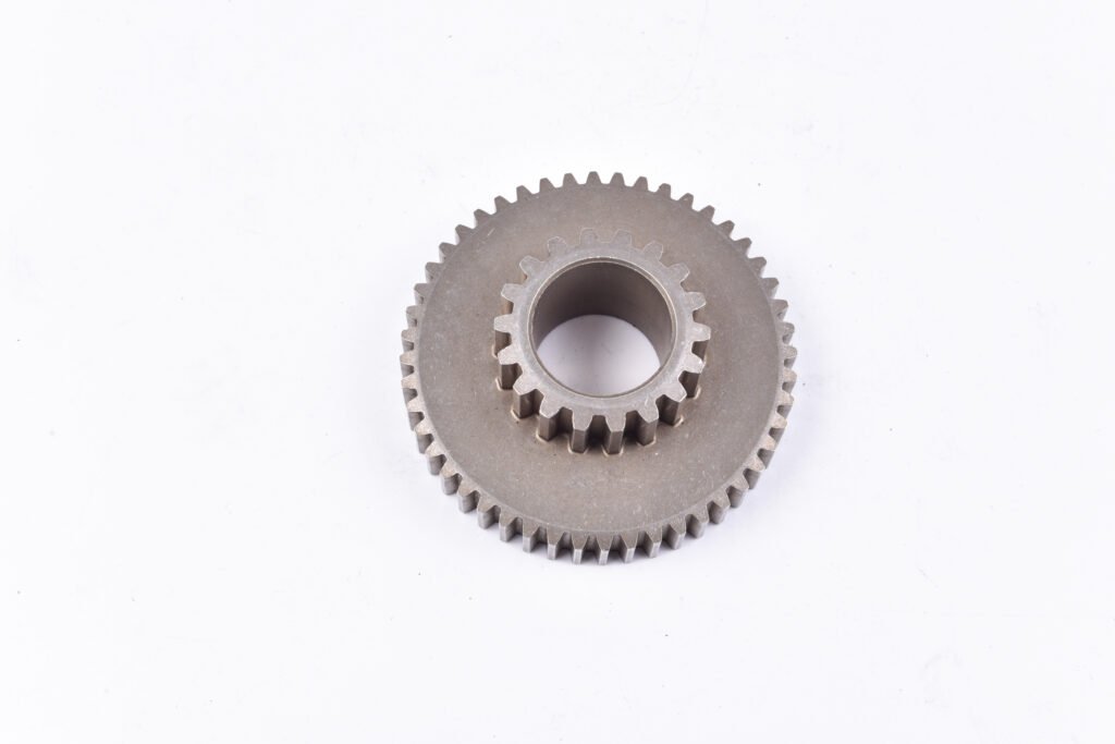
We run gear blanks and bushings with dead-parallel walls every shift. On the 500 t Dorst press the lower punch lifts the compact at a set speed and the die wall never sees an ejection load. A designer who adds 2° “to be safe” on a housing OD hasn’t made ejection safer – he has taken that OD off the sizing path and widened its tolerance. Straight walls are not a compromise in PM. They are the reason PM holds ±0.025 mm after sizing on features plastics can’t.
The Three Places Draft IS Required
1. Bosses and studs formed in punch cavities: 7-15° per side
A boss is formed by a pocket machined into the face of an upper or lower punch. Unlike a die wall, that pocket does slide over the compact at ejection – the powder inside it springs back slightly and grips the pocket walls. MPIF guidance: boss draft of at least 12° per side to prevent sticking, boss depth no more than about 15% of overall part height. In practice we quote 7-15° depending on the boss diameter and depth; a shallow, wide boss survives at the low end, a deep narrow boss wants the high end.
2. Grooves and slots pressed from punch-face projections: up to 12°
Rectangular grooves formed by projections on the punch face are limited to about 15% of part length in depth (curved or semicircular grooves up to 20%), with draft of up to 12° on surfaces parallel to the pressing direction and radiused corners. Beyond those limits the punch projection becomes fragile tooling and the powder can’t fill the corner.
3. Large chamfers: geometry that avoids powder wedging
The standard bushing lead chamfer is 30-45° with a 0.13-0.38 mm flat – the flat keeps a fragile feather edge off the punch. When a drawing asks for a large-angle chamfer formed by a beveled die or core rod, powder wedges against the angle during fill and the fill shoe needs extra strokes, so the chamfer angle becomes a cycle-time question. We size it in DFM, not on the shop floor.
From the DFM desk
Draft fixes after tooling are the ones that hurt. A customer sent us a sensor housing with a 6 mm boss at 0° – their CAD checklist was copied from a plastics template, so nobody questioned it. First article cracked at the boss root on every lot. The fix cost them a punch rework in D2 tool steel (3 weeks) plus 10° draft. One DFM note before kickoff would have made it a free, correct tool on the first build.
What Failure Looks Like on the Press Floor
On the compaction line, skipped draft in punch cavities shows up quickly through three clear defects, in the order they appear:
- Green cracking at ejection. The compact exits the die at 6.4-6.8 g/cm³ green density with a green strength of roughly 15-25 MPa – about the strength of a chalk stick. A wall that grips it opens hairline cracks at stress concentrations: boss roots, groove corners, flange junctures. Hard to see green, obvious after sintering.
- Sticking and tearing. Grip deeper and the boss tears off and stays in the punch cavity. Operators respond with more zinc stearate in the powder mix or a slower ejection stroke – both of which drop the cycle rate, and the piece price follows.
- Dimensional drift. Ejection force fluctuating lot to lot shows up as bore and OD variation. When we trace an unstable Cpk on a feature, the tool sometimes tells us the designer added a taper where the sizing operation expected a parallel wall.
Draft Angle vs. Sizing and Tolerance: The Trade Nobody Writes Down
Here is where the top-20 guides stop short. Sizing – the re-press that brings critical features to IT6-IT7 – works by full-face contact between the sizing tool and the part. A drafted wall contacts the tool on an edge or a line. A taper cannot be sized to a tight tolerance.
So the real decision tree for a designer looks like this:
- Feature needs IT6-IT7 (a bearing bore, a spline, a valve seat)? → keep the wall parallel and add a sizing operation. No draft.
- Feature is a boss or groove inside a punch cavity? → draft 7-15°, and keep the tolerances on it at IT8-IT9.
- Feature is an undercut, annular groove, side hole, or thread? → no draft saves you – it still can’t be pressed. Machine it after sintering, and price that operation.
At JH PM we hold ±0.05 mm as-sintered on critical dimensions and ±0.025-0.05 mm after sizing on selected features. Every dimension on a drafted surface sits outside that sizing path – we list the tolerance per feature in the 48-hour DFM note so the trade is on paper before tooling money moves.
Powder Metallurgy Draft Angle Rules: Summary Table
| Feature | Draft required? | Typical draft | Key limit | Ejection / density condition | Tolerance reality |
|---|---|---|---|---|---|
| Outer walls (die walls) | No – straight is correct | 0° | — | Ejection load carried by lower punch; wall friction only during densification to 6.4-7.2 g/cm³ | Sizeable, IT6-IT7 after sizing |
| Bores / holes in pressing direction | No | 0° | Core rod straightness governs | Core rod withdrawal at controlled speed; friction against 15-25 MPa green strength compact | Sizeable, IT6-IT7 |
| Blind holes, tapered holes, D-holes, splines | No | 0° | — | Core-rod buckling risk above ~8:1 length-to-diameter | Sizeable |
| Bosses / studs (punch cavities) | Yes | 7-15° per side | Depth ≤ ~15% of part height | Springback grips cavity wall; sticking rises with density gradient at boss root | IT8-IT9 |
| Rectangular grooves (punch-face projections) | Yes | up to 12° parallel walls | Depth ≤ 15% of part length; radiused corners | Punch projection carries full compaction tonnage; corner fill depends on powder flow | IT8-IT9 |
| Curved / semicircular grooves | Preferred | up to 12° | Depth ≤ 20% of part length | Round punch projection carries the same tonnage limit | IT8-IT9 |
| Lead chamfers on bores | N/A (angle is the feature) | 30-45° + 0.13-0.38 mm flat | Avoid feather edges | Flat prevents chipping of punch edge at full tonnage | — |
| Large-angle chamfers (beveled tool) | Geometry-dependent | — | Powder wedging during fill | Fill shoe needs extra strokes; cycle time rises | Case by case |
| Undercuts, annular grooves, side holes, threads | Cannot be pressed | — | Machining after sintering | Block straight ejection; compact at 15-25 MPa green strength cannot clear a sideways restraint | Machining tolerances |
How to Review Draft Angle on Your Drawing (Engineer’s 6-Step Method)
Step 1 – Fix the pressing direction
Rotate the model so the largest flat face is perpendicular to the press axis. Every surface parallel to that axis is a die wall – straight walls are free.
Step 2 – Classify every vertical wall
Die wall (no draft) / punch-cavity wall (boss, stud, countersink – 7-15°) / groove wall (≤12°, depth-limited) / non-pressable (machine later).
Step 3 – Check bosses against 15% rule
Boss depth ≤ ~15% of part height, 7-15° draft. Deeper bosses need special tooling and risk density variation at the root.
Step 4 – Resolve draft vs. sizing conflicts
Any IT6-IT7 dimension needs a parallel, sizeable surface. Drafted wall or tight tolerance – pick one before tooling.
Step 5 – Move features to secondary ops
Undercuts, annular grooves, side holes, threads. Price machining in – or redesign it out (two pressed steps instead of one groove).
Step 6 – Freeze geometry & write DFM
48-hour written DFM: draft per feature, tolerance per feature, density target, secondary ops, flagged ejection risks.
FAQ – Powder Metallurgy Draft Angle
Do powder metallurgy parts need a draft angle?
Most need none. The compact is ejected by the lower punch, not pulled past a wall, so straight die walls release cleanly. Draft is only required where a feature is formed in a punch cavity that must release over the compact – bosses, certain grooves, deep steps – where 7-15° per side is typical.
Why does injection molding need draft but powder metallurgy mostly does not?
In injection molding the part is pulled out of a cavity and slides along every molded wall, so parallel surfaces drag and scar. In rigid-die PM the compact is pushed out from below and the ejection load is carried by the punch face, not wall friction. The processes look similar in the die but unload completely differently.
Where does a PM part actually need draft angle?
Three places. Bosses formed in punch cavities need 7-15 degrees per side, and the boss depth should stay under about 15 percent of part height. Rectangular grooves pressed from punch-face projections need up to 12 degrees on surfaces parallel to the pressing direction, with groove depth under 15 percent of part length (20 percent for curved grooves). Large chamfers above roughly 30 degrees need draft-compatible die geometry to avoid powder wedging during die fill.
What happens if you skip draft on a PM boss?
The boss sticks in its punch cavity at ejection: green cracking at the boss root, a boss that tears off and stays in the tool, or dimensional drift as operators slow the cycle to survive. Fixing it after tooling means punch rework – weeks of lead time and a tooling change charge.
Does draft angle affect PM tolerances and sizing?
Yes. A drafted wall cannot be sized flat – the sizing tool contacts it on an edge – so dimensions on drafted surfaces hold IT8-IT9 rather than IT6-IT7. If a drawing calls IT6 on a drafted wall, we either revert to a parallel wall with sizing, or accept the wider tolerance. We flag this in the 48-hour DFM note.
How much does draft angle cost in a PM quote?
Usually nothing – most PM parts need no draft, which is part of PM’s cost advantage. Draft costs appear when boss draft adds punch complexity, large chamfers slow the press cycle, or a no-draft-possible feature (groove, undercut, thread) requires post-sinter machining.
Is the “zero draft” rule true for MIM too?
No. Metal injection molding ejects a feedstock part from a mold like plastic, so MIM parts do need draft – typically 0.5-1° minimum, more on deep cavities. The zero-draft rule belongs specifically to rigid-die press-and-sinter. If you’re comparing PM and MIM for a part, draft is one of the design-rule differences to check early.
Your CAD Checklist Was Probably Written for Plastics. Ours Isn’t.
Most draft-angle mistakes we see come from design templates borrowed from injection molding – a 2° taper on a wall that should stay parallel, a boss at 0° that cracks at the root on every lot. Both are one-line fixes on the drawing and three weeks of punch rework after tooling.
Send us the STEP file or 2D PDF with your load case and annual volume. Within 48 hours you get a written DFM note: draft angle per feature, achievable tolerance per feature (as-sintered ±0.05 mm, sized ±0.025-0.05 mm), density target, and any non-pressable geometry flagged with its machining cost. IATF 16949, 19 presses from 6 to 1,000 t, tooling built in-house.