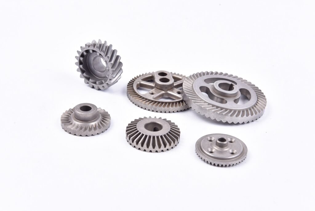
Sintered Parts Porosity and Density: Why 85–92% Density Is a Feature, Not a Flaw
A design engineer sent us a drawing last quarter with a note we still argue about internally: “Density 7.85 g/cm³ min, no porosity.” It was a self-lubricating bushing. He had copied the density callout off a bar-stock drawing, and in doing so specified away the single property that made the part work. A bushing with no porosity cannot hold oil. It would have seized on the shaft inside a week.
That note is why this page exists. Buyers and designers look at “85 to 92 percent of theoretical density” on a sintered part quote and read it as a defect disclosure. Sometimes it is. More often it is the process working exactly as intended, and the pores are doing a job your drawing never asked for. Here is what the numbers mean, what porosity costs you, what it gives you, and when to fight for every tenth of a gram per cubic centimeter.
| Metric | Value |
|---|---|
| Iron-base as-sintered density | 6.6 to 7.2 g/cm³ (85 to 92% of theoretical) |
| As-sintered porosity | 8 to 15%, mostly open (interconnected) |
| After sizing or re-press | +0.1 to 0.3 g/cm³, locally on sized faces only |
| Steam treatment | No density gain; seals near-surface pores, +2 to 4% weight |
| Copper infiltration | To roughly 95% of theoretical; seals pores as a side effect |
| Oil-impregnated bushing porosity | 15 to 25 vol% (a design requirement, not a defect) |
| Density reporting | Water displacement per ASTM B328, every lot, MES traceable |
| MOQ | From 2,000 pcs; economic breakeven around 10,000 |
| Certifications | IATF 16949:2016, ISO 9001:2015; PPAP, MPIF-aligned |
What Porosity in Sintered Parts Actually Is
Start with the process, because the pores are not an accident. They are the residue of how powder metal parts are made.
A press-and-sinter part starts as loose powder compacted in a die at room temperature. At that stage the particles touch each other at points, like a pile of gravel. The press gives the part enough green strength to hold its shape, but the particles are still distinct bodies with air between them. Sintering then heats the part to a temperature just below melting, and the atoms at each particle-to-particle contact start to migrate. Necks grow between particles, the pores between them shrink and round off, and the part gains most of its strength in the furnace.
But the shrinkage stops short. Sintering closes maybe half to two-thirds of the original void space before the process stalls,, grain boundaries pin the pores, and driving them fully shut costs furnace time and temperature that most parts do not justify. What remains is 8 to 15% porosity in a typical iron-base part, and it sits mostly as open, interconnected porosity rather than isolated closed pores.
That distinction (open versus closed) matters more than the total percentage. Open pores connect to the surface. They are what let a bushing wick oil, what let plating solution bleed back out of an unsealed part, and what read as deep valleys on a profilometer trace (the same story our sintered parts surface finish guide walks through). Closed pores are trapped voids inside the part; they affect density but nothing you can touch.
Why 85–92% Is the Sweet Spot, Not a Shortfall
Here is the part that surprises people: full density is not the goal of the process. It is a cost trap. Getting the last few percent of density out of a sintered part requires either infiltration, high-temperature sintering, or powder forging, and each one adds cost that most applications get nothing back for.
The pore volume is not wasted material. It is inventory. Depending on the part, it can be spent on:
- Self-lubrication. Oil-impregnated bushings are specified at 15 to 25% interconnected porosity by design. The pores hold 18 to 30% of their own volume in oil, and the bearing feeds it to the shaft as it runs. No greasing, no maintenance port, for the life of the assembly. This is a sixty-year-old, thoroughly proven application, the porosity is the product.
- Damping. Residual porosity dissipates vibration energy. Gear meshes and pump housings in noise-sensitive applications run quieter as PM parts than as machined equivalents, all else equal.
- Infiltration readiness. Open porosity is a network of capillaries. Copper infiltration uses it deliberately, wicking molten copper into the part to seal it and boost density to roughly 95%, only in the areas that need it, if you design the infiltrant path that way.
- Filtration. At the extreme end, sintered porous bronze and stainless discs are made as flow-control elements, with porosity engineered to a target permeability rather than minimized.
Where does porosity actually hurt performance? Mostly not where buyers assume. Static tensile strength of a well-made iron-base sintered part runs around 80 to 90% of an equivalently alloyed wrought steel, for a bracket, a gear running in a greased mesh, or a camshaft sprocket, that margin is irrelevant and nobody notices. The honest list of what porosity costs comes next.
What Porosity Costs You (The Honest List)
We would rather a designer over-ask on this section than under-ask. These are the four places porosity genuinely bites, with what to do about each.
- Fatigue strength. This is the big one, and it is worse than the static numbers suggest. Pores act as pre-existing crack starters, so fatigue strength drops harder than tensile strength, a porous part that holds 85% of wrought tensile may hold considerably less of the wrought fatigue limit at high cycle counts. If your part sees millions of high-stress cycles, a connecting rod, a heavily loaded gear tooth flank, you are into copper infiltration, higher-density processing, or a candid conversation about whether wrought is the right route. We have that conversation on about every fifth gear drawing we quote.
- Pressure sealing. Open porosity is a leak path. A hydraulic manifold, a pneumatic cylinder end cap, any face holding fluid under pressure: pores will weep. The fixes are localized, machine the sealing face (which smears surface pores shut), infiltrate, or steam-treat for low-pressure duty. The surface finish angle is covered on our sintered parts surface finish page, because pores and finish are the same problem wearing two hats.
- Corrosion initiation. Open pores trap electrolyte and crevice-corrode from the inside. Steam treatment’s magnetite layer, phosphate coatings, or plating after pore sealing handle this, the treatment section of the surface finish page covers which does what.
- Magnetic performance. For soft magnetic PM parts (rotor and stator laminations, sensor cores), every pore is a demagnetizing void that lowers permeability. High-density processing or, increasingly, powder-forged routes matter here in a way they don’t for structural parts.
Note what is not on that list: yield strength under normal duty, dimensional stability, machinability (porous parts machine acceptably, with the pore-interrupted-cut caveat from the finish page), or thermal conductivity in any application that matters. Most structural PM parts live and die on none of these four.
How to Increase the Density of Sintered Parts
When you do need more density, here is the ladder, cheapest first:
| Method | Density gain | Cost and trade-off |
|---|---|---|
| Higher compaction pressure | +0.1 to 0.2 g/cm³ | Limited by press tonnage and die wear; cheapest lever |
| Prealloyed powder + high-temp sinter | +0.05 to 0.15 g/cm³ | Furnace temperature cost; better particle bonding |
| Sizing / re-press / coining | +0.1 to 0.3 g/cm³ local | Local only, sized faces, not the whole part |
| Copper infiltration | To ~95% of theoretical | Adds infiltrant cost; seals pores as a side effect |
| Powder forging | ~99%+ (≈7.8 g/cm³) | Expensive tooling; reserved for fatigue-critical parts |
Two traps on this ladder. First, sizing raises density only where the die touches, it is a surface treatment for density, not a bulk one, and quoting a whole-part density gain from sizing is a spec error we see on real drawings. Second, steam treatment raises weight, not density: the magnetite fills near-surface pores and adds 2 to 4% mass, but the part’s structural porosity is untouched. Do not let a weight check on a steam-treated part fool you into thinking it got denser.
Designing with Porosity on Purpose
This is the section for the person holding the CAD model. The material’s porosity is controllable, locally and deliberately, and the parts that use it well treat density as a drawing parameter rather than a footnote.
The core move is functional zoning: one part, two density requirements. Take a sintered camshaft bearing journal assembly, the bushing wants 20% porosity for oil storage, the mounting flange wants maximum density for bolt preload, and nothing about the press-and-sinter process stops you from having both. Compare that to machining the same assembly from two wrought pieces and joining them, and the PM route usually wins on cost and often on function. The same logic is why a sintered power tool gear can carry torque at the hub while the outer rim is sized tight for the bearing seat, two density requirements, one part.
How We Control and Report Density
Density on a sintered part is measured by water displacement, weigh dry, saturate, weigh suspended, weigh wet, per ASTM B328, and it is a whole-lot measurement, not a sampling of lucky parts. Our furnace zones are thermocouple-mapped and the press tonnage per program is locked in the MES, so a density number traces back to the exact press setup and furnace run that made the part.
Every lot report we ship includes density where the drawing calls it out, alongside the CMM dimensional data and, on finish-callout parts, the Rk/Rpk surface data described on our surface finish page. Density and porosity data ship on every lot where the drawing asks, standard, no need to request it. The same MES lot trail is what the quality page walks through for IATF 16949 and PPAP submissions.
Designing with Porosity: The 5-Step DFM Checklist
Here is the working list we walk designers through, ordered so each step is a drawing mark that has to be made before tooling is ordered. (The five steps also work as a Google HowTo, that is by design.)
- Put a density band on the drawing, not a single number. “6.8 to 7.2 g/cm³” is producible; “7.0 g/cm³” is a coin flip. Specify by volume where it matters: pores on this face, density on that one.
- Flag fatigue-loaded zones explicitly. If a section sees high-cycle stress, say so on the print. That single note changes our powder selection, compaction plan, and possibly the whole route, and it is invisible unless you write it down.
- Call out sealing faces for machining or infiltration. Do not leave a pressure boundary to chance. Mark it, and the DFM will price the cheapest way to close it.
- For oil-impregnated parts, specify oil content, not porosity. The functional requirement is 18 to 30% oil by volume (per MPIF 35 conventions); porosity is how we get there. Specifying porosity directly invites a part with the wrong pore structure.
- Ask what the density report covers. Bulk density per ASTM B328 water displacement, per lot, with the same MES traceability as your dimensional data. If a supplier cannot tell you how they measured, the number is decorative.
Key Takeaways
Iron-base sintered parts land at 6.6 to 7.2 g/cm³, 85 to 92% of theoretical density, and that is the process working, not failing. Porosity is a feature when the design spends it (self-lubrication, damping, infiltration) and a liability when the design ignores it (fatigue zones, sealing faces). Fatigue is where porosity hurts most; sealing is where it leaks. Density is a ladder, compaction, sizing, infiltration, forging, and the trick is buying only the rung the part needs.
The expensive design error is not porosity. It is copying a wrought-steel density callout onto a sintered part, or specifying full density where pores were doing a job. Send us the drawing with the working surfaces and load zones marked, and we will tell you where to keep porosity, where to buy density, and what each rung costs, inside 48 hours from a free DFM review.
Send the Drawing. We Will Mark Where to Keep Porosity, Where to Buy Density, and What Each Rung Costs.
Attach the drawing and note the oil-retention zones, sealing faces, and any high-cycle load areas. We will route the part to the right rung of the density ladder and send tolerance and finish review back together, within 48 hours, free.
Request a Free DFM ReviewFAQ: Sintered Parts Porosity and Density
What is the typical density of sintered steel parts?
Iron-base press-and-sinter parts typically hold 6.6 to 7.2 g/cm³, which is 85 to 92% of theoretical density, depending on alloy and compaction pressure. Sizing adds 0.1 to 0.3 g/cm³ locally on sized faces, and copper infiltration reaches roughly 95%. Oil-impregnated bushings are specified at 15 to 25% porosity by design, for those parts, the lower density is the requirement.
Why is porosity in sintered parts sometimes desirable?
Because the pore volume is functional inventory. Oil-impregnated bushings need 15 to 25% interconnected porosity to hold lubricant. Residual porosity damps vibration in gear meshes and housings. Open pores are the network that copper infiltration wicks through, and sintered porous discs are made as filters with porosity engineered to a target. Specifying full density on those parts removes the property you bought the part for.
How does porosity affect the strength of sintered parts?
Static tensile strength runs around 80 to 90% of equivalently alloyed wrought steel, which is fine for most structural duty. Fatigue strength drops harder, because pores act as pre-existing crack starters at high cycle counts. For fatigue-critical parts, the counters are higher compaction density, copper infiltration, or powder forging, and flagging fatigue zones on the drawing so the process is chosen accordingly.
How do you increase the density of a sintered part?
Five routes, cheapest first: higher compaction pressure (+0.1 to 0.2 g/cm³), prealloyed powder with high-temperature sintering (+0.05 to 0.15), sizing or re-pressing for local gains of 0.1 to 0.3 g/cm³ on contacted faces, copper infiltration to roughly 95% of theoretical, and powder forging at 99%+ for fatigue-critical parts. Note that steam treatment adds weight and seals pores but does not raise structural density.
Does sizing or steam treatment make a sintered part fully dense?
No. Sizing raises density only where the sizing die contacts the part, it is a local, surface-level gain. Steam treatment forms a magnetite layer that fills near-surface pores and adds 2 to 4% weight, but the part’s internal porosity is unchanged. To genuinely approach full density, the routes are infiltration (to ~95%) or powder forging (99%+). For most structural parts, neither is needed, the as-sintered density band already covers the duty.