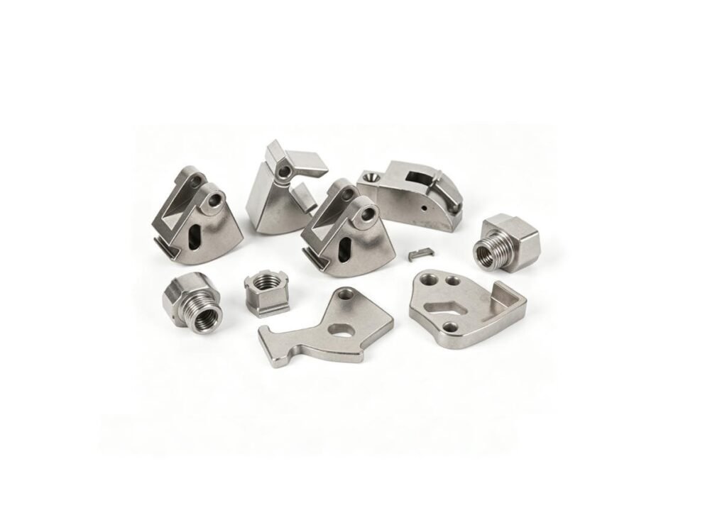
Sintered FD-0405 Diffusion-Alloyed Steel: Properties, Applications & Selection Guide
An engineering selection guide to sintered FD-0405 diffusion-alloyed steel per MPIF Standard 35-SP (2024 Edition): understanding diffusion metallurgy, evaluating minimum versus typical property boundaries, and determining application trade-offs against conventional admixed PM grades[cite: 5].
Quick Material Facts: FD-0405
| Material Family | Diffusion-alloyed PM steel |
|---|---|
| Base System | Iron-based |
| MPIF Standard | Standard 35-SP (2024 Edition) |
| Primary Engineering Role | Structural PM components |
| Alloying System | Diffusion-bonded Ni-Cu-Mo onto iron particles |
| As-Sintered Condition | Available where specified |
| Heat-Treated Condition | Available for applicable grades |
| Typical Application Direction | Gears, sprockets, cams, structural drivetrain parts |
1. What Is FD-0405 in Powder Metallurgy?
The alphanumeric designation FD-0405 follows the formal classification system established by the Metal Powder Industries Federation (MPIF) and recognized in ASTM B783. The code provides a standardized classification framework, but it does not replace the full chemical composition table or detailed mechanical property requirements.
Why the Complete Material Designation Matters
MPIF material designation guidance explicitly explains that for ferrous materials, the prefix and numerical code identify the material family, the major alloying constituent, and the nominal combined-carbon level. Permitted ranges for secondary alloying elements (such as copper and molybdenum) and trace elements are defined in the governing chemical-composition table.
The trailing numerical suffix indicates specified minimum strength in thousands of pounds per square inch ($10^3\text{ psi}$ or ksi). For example, in FD-0405-55, the suffix denotes a specified minimum 0.2% offset yield strength of 55 ksi (~380 MPa) in the as-sintered state. In FD-0405-115HT, the suffix indicates a specified minimum ultimate tensile strength of 115 ksi (~790 MPa) in the heat-treated condition. The numerical suffix does not represent material density.
2. What Makes Diffusion-Alloyed FD-0405 Different?
Ferrous powder metallurgy materials can be produced via elemental admixing, prealloying, or diffusion alloying. FD-0405 belongs to the diffusion-alloyed PM steel category. Commercial diffusion-alloyed powders may utilize different proprietary powder systems, but all share a fundamental metallurgical architecture that distinguishes them from conventional mixes.
Conventional Admixed Powder Route
In conventional admixed steels, loose elemental powders are mechanically blended. Because elemental particles vary in particle size and specific gravity, unbonded mixes carry inherent risks of particle segregation during bulk handling, container transport, and vibratory feeder shoe movements.
Diffusion-Alloyed Powder Route
In diffusion-alloyed powders, fine alloying particles are thermally bonded onto the surfaces of compressible iron particles during raw powder manufacture. This thermal bonding anchors the alloy constituents to the host particles.
Why Powder Morphology Matters
- Segregation Resistance: Diffusion alloying reduces the risk of elemental segregation during powder handling compared with conventional admixed elemental additions, supporting consistent chemical distribution across high-volume production lots.
- Preserved Compressibility: Unlike fully prealloyed powders where alloying elements are dissolved in the melt and work-harden the iron lattice, diffusion-alloyed powders retain a soft, unalloyed iron core. This allows high green density to be achieved at conventional pressing pressures.
- Sintering Response: During sintering, alloying additions diffuse inward from the particle boundaries, creating a heterogeneous, multi-phase microstructure designed for strength and toughness.
3. FD-0405 Chemical Composition
The FD-0405 designation identifies the material family and nominal coded composition; the applicable MPIF/ASTM chemistry table defines the permitted composition. Production lot acceptance is governed by the chemical composition envelope in MPIF Standard 35-SP (2024 Edition) and ASTM B783:
| Element | MPIF 35-SP Permitted Range (wt. %) | Engineering Role in Sintered Matrix |
|---|---|---|
| Iron (Fe) | Balance | Base matrix providing structural ductility and compressibility. |
| Nickel (Ni) | 3.50% – 4.50% | Diffusion-bonded to particle surfaces; enhances hardenability and dynamic impact toughness. |
| Copper (Cu) | 1.25% – 1.75% | Forms transient liquid phase during sintering at $\sim1,085^\circ\text{C}$, strengthening interparticle necks. |
| Molybdenum (Mo) | 0.40% – 0.60% | Hardenability agent; retards pearlite transformation and supports through-hardening in heavier sections. |
| Combined Carbon (C) | 0.30% – 0.60% | Admixed as graphite; establishes matrix strength and enables martensitic transformation during heat treatment. |
| Other Elements | 2.0% max (Acid insolubles $\le 0.5\%$) | Residual oxides, trace deoxidizers, or process additions per applicable specification. |
Combined Carbon Requirement: Acceptance testing requires determining combined carbon (metallurgically dissolved carbon within the iron lattice) per ASTM methods, rather than total added graphite. Free graphite residing in pore cavities does not contribute to matrix tensile strength.
4. FD-0405 Density and Porosity
Powder metallurgy steel properties cannot be interpreted independently from density. Density is not simply a quality number; in PM steels, it is closely connected to porosity, and porosity directly influences mechanical properties. MPIF notes that PM microstructures differ from wrought materials partly because of pores whose size, shape, and distribution depend on density, alloy system, and processing method.
Increasing density generally reduces the amount of interconnected porosity and can improve strength, fatigue behavior, and impact performance, but the relationship is material- and condition-dependent. For structural FD-0405 components, sintered densities typically range from 6.8 to 7.3 g/cm³:
At $7.2\text{ g/cm}^3$, FD-0405 operates at approximately 92% of theoretical density. The remaining 8% consists of residual pores that influence cross-sectional load bearing and notch sensitivity.
5. Mechanical Properties by Density and Condition
To avoid misinterpreting mechanical capabilities, properties must be evaluated based on the specific processing condition (As-Sintered vs. Heat-Treated). In accordance with MPIF Standard 35-SP and ASTM B783, a clear distinction must be maintained between contractual minimum values (the standard requirement for lot release) and typical property values (reference data for engineering design):
Table 5A: As-Sintered FD-0405 Mechanical Properties
| MPIF Grade Callout | Min. Sintered Density | Specified Min. Yield Strength | Typical Tensile Strength (UTS) | Typical Elongation ($1.0”$) | Typical Apparent Hardness | Typical Unnotched Charpy Impact |
|---|---|---|---|---|---|---|
| FD-0405-45 | $6.8\text{ g/cm}^3$ | 310 MPa (45 ksi) | 450 MPa (65 ksi) | 1.5% | 72 HRB | 11 J (8 ft·lbf) |
| FD-0405-55 | $7.0\text{ g/cm}^3$ | 380 MPa (55 ksi) | 550 MPa (80 ksi) | 2.0% | 78 HRB | 16 J (12 ft·lbf) |
| FD-0405-65 | $7.2\text{ g/cm}^3$ | 450 MPa (65 ksi) | 650 MPa (94 ksi) | 2.5% | 84 HRB | 22 J (16 ft·lbf) |
Table 5B: Heat-Treated (Quenched & Tempered) FD-0405 Properties
| MPIF Grade Callout | Min. Sintered Density | Specified Min. Tensile (UTS) | Typical Yield Strength | Typical Elongation ($1.0”$) | Typical Apparent Hardness | Typical Unnotched Charpy Impact |
|---|---|---|---|---|---|---|
| FD-0405-100HT | $6.8\text{ g/cm}^3$ | 690 MPa (100 ksi) | 690 MPa (100 ksi) | < 0.5% | 28 HRC | 8 J (6 ft·lbf) |
| FD-0405-115HT | $7.0\text{ g/cm}^3$ | 790 MPa (115 ksi) | 790 MPa (115 ksi) | < 0.5% | 32 HRC | 12 J (9 ft·lbf) |
| FD-0405-135HT | $7.2\text{ g/cm}^3$ | 930 MPa (135 ksi) | 930 MPa (135 ksi) | < 0.5% | 36 HRC | 16 J (12 ft·lbf) |
Standard Data Boundary: Bold values represent mandatory contractual minimum requirements per MPIF Standard 35-SP (2024 Edition). Non-bold values are typical engineering reference values obtained from standard PM test specimens. Actual properties achieved on production parts will vary based on localized section thickness, density distribution, and thermal processing conditions.
6. Microstructure and Porosity
The microstructure of sintered FD-0405 is intentionally heterogeneous. Because conveyor sintering cycles operate below the melting point of nickel ($1,455^\circ\text{C}$) and molybdenum ($2,623^\circ\text{C}$), alloying occurs via solid-state diffusion, creating distinct microstructural zones:
- Core Iron Matrix: The centers of the host iron particles transform to pearlite, ferrite, or bainite depending on carbon level and cooling rate.
- Alloy-Rich Boundaries: As nickel and molybdenum diffuse inward from particle surfaces, alloy-concentrated networks form along particle boundaries and around pore necks.
- Nickel-Rich Regions: Localized areas high in nickel concentration remain as retained austenite or martensite-austenite mixtures, contributing to ductility and crack-arrest capability.
- Pore Morphology: Transient liquid copper formation during sintering promotes neck growth and pore rounding, reducing sharp micro-notches that would otherwise act as stress concentrations.
7. Heat Treatment and Hardenability
Diffusion-alloyed PM steels can offer a useful combination of hardenability, density control, and dimensional stability. With combined carbon between 0.3% and 0.6%, FD-0405 responds readily to thermal hardening:
As-Sintered vs. Heat-Treated Processing Routes
- As-Sintered: Used where moderate strength and dimensional stability are needed at minimum cost. The structure consists of pearlite, ferrite, and alloy-rich phases.
- Quench and Temper: Austenitized ($840^\circ\text{C}\text{–}870^\circ\text{C}$), oil quenched, and tempered ($175^\circ\text{C}\text{–}250^\circ\text{C}$) to produce tempered martensite and maximize tensile strength.
- Carburizing / Surface Hardening: Applied where high surface contact fatigue resistance is required, forming a high-carbon martensitic case while preserving core toughness.
Why Hardenability Matters in Thick Sections
The combination of 4% nickel and 0.5% molybdenum retards the pearlite transformation, providing deeper hardenability than plain iron-carbon or copper-steels. In components with varying cross sections, this suppresses soft ferrite-pearlite formation at the core during quenching.
Managing Heat-Treatment Distortion
Heat-treatment distortion remains dependent on part geometry, density distribution, furnace conditions, quenching severity, and post-treatment processing. To control distortion, tooling designs must incorporate compensatory dimensional allowances established during engineering DFM reviews.
8. How Are FD-0405 Sintered Parts Manufactured?
Production of custom FD-0405 parts follows an established press-and-sinter workflow[cite: 5]:
- Diffusion-Alloyed Powder Preparation: Base powder with pre-bonded alloy additions is conditioned with graphite and organic pressing lubricants[cite: 5].
- Powder Blending: Homogenization to ensure uniform lubricant and carbon distribution[cite: 5].
- Compaction: Uniaxial pressing at 500 to 750 MPa establishes the green compact geometry and target density[cite: 5].
- Controlled-Atmosphere Sintering: Sintered at $1,120^\circ\text{C}\text{–}1,150^\circ\text{C}$ in protective atmospheres (dissociated ammonia, nitrogen-hydrogen, or endothermic gas) with continuous dew point logging[cite: 5].
- Sizing / Secondary Operations (Optional): Cold re-pressing in the as-sintered state when critical features demand tight radial tolerances[cite: 5].
- Heat Treatment: Quenching and tempering or surface carburizing per drawing specifications[cite: 5].
- Final Inspection: CMM dimensional layout, density testing per ASTM B962, and hardness audits[cite: 5].
9. DFM Guidelines for FD-0405 Parts
To ensure consistent manufacturability, component designs should follow established PM design practices:
- Pressing Direction & Undercuts: Geometry must permit straight-line tool withdrawal. Cross-holes, undercuts, and radial grooves require secondary machining.
- Section Thickness Transitions: Avoid abrupt transitions between heavy hubs and thin web sections to minimize density variation and localized sintering stresses.
- Fillet Radii on Gear Teeth: Tooth root fillets should maintain a minimum radius of 0.25 to 0.40 mm to eliminate punch stress raisers and avoid micro-cracks in the green compact.
- Machining & Distortion Allowances: Allow sufficient stock (typically 0.25 to 0.50 mm) on faces requiring post-heat-treatment finish grinding to clean up quench movement.
10. Where Is FD-0405 Used?
FD-0405 can be considered for structural applications when its property and processing requirements match the design load case:
- Gears and Sprockets: Planetary gear sets, timing sprockets, and drive pinions subjected to cyclic tooth-bending loads and contact stresses.
- Automotive Drivetrain & Safety Components: Synchronizer hubs, clutch plates, and transmission drive flanges. MPIF technical documentation records an automotive braking-system rack that was warm-die compacted from FD-0405 and case hardened, demonstrating the material’s suitability for safety-critical automotive structural service.
- Cams and Pawls: Heavy-duty ratchet pawls and multi-track cams experiencing repetitive impact and surface contact.
- Structural Hubs & Industrial Components: Fluid power valve plates and heavy-duty industrial pump components requiring deep hardenability and structural integrity.
11. FD-0405 vs. FN-0205: Engineering Differences
Selecting between FD-0405 (Diffusion-Alloyed) and FN-0205 (Elemental Admixed Nickel-Steel) involves balancing hardenability, mechanical capacity, and raw material cost:
| Engineering Factor | FD-0405 (Diffusion-Alloyed Steel) | FN-0205 (Admixed Nickel-Steel) |
|---|---|---|
| Powder Alloying Approach | Alloying additions diffusion-bonded to particle surfaces | Mechanical blend of elemental iron, nickel, and graphite |
| Alloy Distribution | Diffusion-bonded alloy envelope around iron core | Dispersed elemental particles relying on in-furnace diffusion |
| Hardenability | High (Enhanced by 4% Ni + 0.5% Mo across heavy sections) | Moderate (Effective for intermediate section thicknesses) |
| Heat-Treated Strength Range | Higher tensile strength potential (e.g., FD-0405-115HT / 135HT) | Standard high-strength range (e.g., FN-0205-105HT) |
| Raw Powder Cost | Higher (Reflects proprietary thermal bonding processing) | Lower (Standard elemental powder blend) |
| Typical Design Question | Do I need higher alloying and deeper hardenability? | Can design requirements be met with a simpler alloy system? |
Selection Direction: If stress modeling demonstrates that FN-0205 satisfies design margins, specifying FD-0405 adds unnecessary material cost. When severe cyclic loads, high tooth-root stresses, or heavy cross sections require greater hardenability, FD-0405 should be evaluated.
12. When Should You Consider a Higher-Alloy PM Steel?
If operational requirements exceed the capability of FD-0405, engineers evaluate an established escalation ladder:
| Design Requirement | Candidate Engineering Direction |
|---|---|
| Moderate structural load | FN-0205 / standard copper-steel (FC-0208) |
| High strength with deep hardenability | FD-0405 / diffusion-alloyed PM steels |
| Eliminating quench distortion on complex gears | Sinter-hardened prealloyed steels (e.g., FLC-4608 / FLN2-4405) |
| Severe surface wear and contact fatigue | FD-0405 with surface densification or case hardening |
| Extreme structural or impact demand | Powder forging (MPIF 35-PF) or wrought alloy steel |
13. Can FD-0405 Parts Be Machined?
Machining strategy depends on density, heat-treatment condition, geometry, tolerance, and required surface finish:
- As-Sintered State: Readily turned, drilled, and tapped using conventional carbide tooling. Machining should be performed in the as-sintered state whenever possible before thermal hardening.
- Heat-Treated State: Machining is restricted to precision grinding, hard turning with PCBN tooling, or bore honing.
- Tooling Considerations: Due to the heterogeneous microstructure containing alloy-rich regions, rigid setups and sharp cutting edges are necessary to prevent tool chatter and premature tool wear.
14. How to Specify FD-0405 on an Engineering Drawing
Writing simply “Material: FD-0405” creates ambiguity during procurement. The drawing or purchase order specification should define the required condition rather than assuming the material designation alone defines every performance requirement:
Example Engineering Specification Structure
Material Specification: MPIF FD-0405-115HT per MPIF Standard 35-SP (2024 Edition)
Processing Condition: Quenched and Tempered (or As-Sintered per FD-0405-55)
Minimum Sintered Density: 7.0 g/cm³ min per ASTM B962 (Archimedes method)[cite: 5]
Apparent Hardness: 30–38 HRC (reference)
Particle Microhardness: 550 HV0.1 min per MPIF Standard 51[cite: 5]
Critical Feature Acceptance: Tooth shear / proof testing per agreed inspection plan.
15. Quality Control & JH PM Manufacturing Capability
ASTM B783 describes chemical analysis, density verification, and mechanical testing as part of the material specification framework. At JH PM (Ningbo Jiehuang Chiyang Electronic Tech) in Shaoxing, quality control for custom sintered components operates under certified quality management systems (IATF 16949:2016 and ISO 9001:2015)[cite: 5]:
| Pressing Capacity | 19 precision automatic PM presses ranging from 6 to 1,000 tons capacity, supporting components of varying tonnage and projected area[cite: 5]. |
|---|---|
| Sintering Infrastructure | 2 continuous sintering furnaces with controlled protective atmospheres to maintain carbon potential and ensure consistent diffusion bonding[cite: 5]. |
| Metrology & Inspection | 3 German Zeiss CMMs validating 3D GD&T features, Archimedes density testing per ASTM B962, and optical metallography benches[cite: 5]. |
| Medical Scope Restriction | Non-implantable surgical device hardware only (explicitly NO ISO 13485 certification; no implantable medical devices)[cite: 5]. |
| Commercial Parameters | MOQ 2,000 pieces; tooling lead time 20 working days; T0 trial samples within 25 working days; DFM reviews returned within 48 hours[cite: 5]. |
16. When Is FD-0405 Not the Right Material?
Design teams should consider another material or process when:
- Required Properties Can Be Met with a Simpler Alloy: If design stresses can be satisfied by conventional copper-steel (FC-0208) or 2% nickel-steel (FN-0205), specifying FD-0405 introduces unnecessary alloy cost.
- Corrosion Resistance Is Mandatory: FD-0405 is a low-alloy carbon steel and will oxidize in corrosive or humid environments; austenitic or martensitic stainless steel PM is required.
- Self-Lubricating Function Is Required: The material is formulated for structural density; parts requiring engineered interconnected porosity for oil impregnation should use standard PM bearing alloys per MPIF Standard 35-SLB.
- Production Volume Does Not Support PM Tooling Economics: For low annual volumes (under 2,000 pieces), tooling amortization may favor CNC machining from wrought bar over dedicated PM tooling[cite: 5].
- Component Geometry Exceeds Compaction Limits: Features with severe cross-axis undercuts or extreme aspect ratios may be better suited for Metal Injection Molding (MIM) or multi-axis machining.
17. Frequently Asked Questions
$item ) : ?>Need Help Selecting FD-0405 for a PM Component?
Send your 2D drawing, 3D CAD model (STEP/IGES), required material condition, annual volume, and critical operating requirements. JH PM can review the design for powder metallurgy manufacturability and provide DFM feedback within 48 hours[cite: 5].
Have a part in mind? Send a drawing and get a DFM review within 48 hours.
Request a quote →