Metal Powder Products: Materials, Applications, and Engineering Guide
How engineering and procurement teams classify, specify, and evaluate components manufactured from metal powders: distinguishing raw particulates from finished sintered parts, matching alloy systems to operational loads, and auditing plant capabilities.
- Feedstock Powders: Atomized iron, copper, stainless steel, and refractory powders sold by weight as manufacturing consumables.
- Engineered Powder Products: Solid near-net-shape components, such as structural gears, self-lubricating bearings, soft magnetic cores, and porous filters, formed via press-and-sinter, metal injection molding (MIM), or thermal consolidation.
- Scope of This Guide: This procurement reference focuses on finished engineered components manufactured from metal powders.
- Baseline Capabilities: Press-and-sinter PM holds ±0.05 mm as-sintered and ±0.025 mm after sizing on critical dimensions, with production economics balancing at annual volumes starting from 2,000 pieces at JH PM.
Key Takeaways
- Material Utilization: Powder-based processes achieve high material efficiency by forming geometries near-net shape, though exact yield depends on part geometry and secondary machining.
- Density Predicts Performance: Sintered density is material-specific (e.g., 6.4 to 7.4 g/cm³ for ferrous parts vs. 5.8 to 6.6 g/cm³ for porous bearings). Density dictates tensile strength, elongation, and fatigue life.
- Geometry Governance: Standard press-and-sinter parts require planar or multi-level features oriented along the pressing vector to permit tool ejection. Transverse holes and undercuts require secondary CNC passes.
- Standards Foundation: Specify component acceptance criteria using MPIF Standard 35, density verification via ASTM B962, and interconnected porosity via ASTM B963.
What Are Metal Powder Products?
In manufacturing specifications, linguistic precision prevents supply chain failure. When buyers issue requests for “metal powder products,” raw powder atomizers interpret this as inquiries for metric tons of atomized steel or copper powder, whereas parts fabricators interpret it as finish-machined components ready for mechanical assembly.
Metal Powders vs. Products Made from Metal Powders
ASTM Committee B09 explicitly separates standardizations into Subcommittee B09.02 on Base Metal Powders (governing particle size distribution, apparent density, and flow rate) and Subcommittees B09.04, B09.05, and B09.11 (governing structural parts, self-lubricating bearings, and MIM components). Finished powder metal components utilize solid-state atomic diffusion during sintering: particles are pressed into close proximity and heated below the liquidus point, causing neck growth across grain boundaries without melting the bulk component into a liquid state.
Metal Powder Products by Part Type
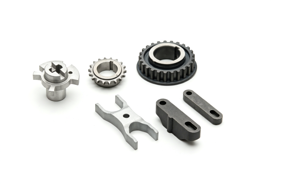
Classifying finished metal powder products by functional geometry and operational duty provides a baseline for matching manufacturing routes to mechanical demands:
| Part Type | Typical Components | Material Grades | Manufacturing Route | Engineering Advantage | Design Constraint |
|---|---|---|---|---|---|
| Gears & Sprockets | Spur gears, planetary gears, timing sprockets, drive cogs | FC-0208, FN-0205, FLN2-4405 | Press-and-Sinter PM | Near-net tooth geometry eliminating hobbing chip waste | Tooth root density must meet bending fatigue limits |
| Bushings & Bearings | Flanged sleeve bushings, spherical self-aligning bearings | SAE 841 Bronze, Sint-A10 | Press-and-Sinter + Vacuum Impregnation | Engineered porosity (18 to 25% oil) for lifetime lubrication | Avoid over-densification; closes interconnected oil pores |
| Structural Parts | Mounting brackets, shift forks, cams, transmission hubs | F-0008, FC-0205, FL-4405 | Multi-Action Press-and-Sinter | Consolidates multi-step profiles into a single 1 to 3 s stroke | Requires continuous draft; zero lateral undercuts |
| Magnetic Components | Solenoid plungers, sensor pole pieces, SMC stator cores | High-purity Iron (F-0000), Fe-P, Fe-Si | Press-and-Sinter / SMC Compaction | High permeability, low coercive force, suppressed eddy currents | Lower tensile strength relative to carbon-alloyed steels |
| Porous Media & Filters | Pneumatic silencers, flame arrestors, filtration discs | Sintered Spherical Bronze, 316L SS | Gravity / Low-Pressure Sintering | Controlled micron-scale pore channels, high temp resistance | Tensile/impact strength secondary to flow permeability |
| Miniature Precision Parts | Surgical tool jaws (non-implant), lock tumblers, micro-levers | MIM 316L, MIM 17-4PH | Metal Injection Molding (MIM) | Complex 3D contours, cross-holes, thin walls under 100 g | 12 to 18% shrinkage requires precision tooling compensation |
Material Families Used in Powder Metal Products
Selecting an alloy for a sintered component involves balancing raw material cost, compressibility, sinterability, and mechanical performance under load. Rather than relying on generic wrought designations (e.g., AISI 1045 or 4140), sintered parts follow standardized powder metallurgy chemistry systems, such as MPIF Standard 35:
| Material Family | Common Grades | Sintered Density | Engineering Characteristics |
|---|---|---|---|
| Iron & Carbon Steel | F-0000, F-0005, F-0008 | 6.6 to 7.1 g/cm³ | Economical base for light-to-medium structural brackets, magnetic pole pieces, and low-stress spacers. |
| Copper-Steels & Nickel-Steels | FC-0208, FN-0205, FN-0208 | 6.8 to 7.3 g/cm³ | Liquid-phase sintering with copper increases yield strength; nickel additions enhance impact toughness and hardenability. |
| Pre-Alloyed & Sinter-Hardened | FL-4405, FLN2-4405, FLC-4608 | 7.0 to 7.4 g/cm³ | High fatigue limits and tooth strength; martensitic transformation achieved directly in furnace rapid-cooling zones. |
| Stainless Steels | SS-304L, SS-316L, SS-410, 17-4PH | 6.5 to 7.2 g/cm³ (PM) / >7.5 g/cm³ (MIM) | Corrosion resistance in marine, food handling, chemical metering, and non-implantable medical instruments. |
| Copper & Bronze Alloys | SAE 841 Bronze (Cu-Sn), Brass | 5.8 to 6.6 g/cm³ (Bearings) | High thermal conductivity, low sliding friction, non-sparking, optimized for liquid lubricant retention. |
| Soft Magnetic Composites | Dielectrically insulated Fe powders | 7.2 to 7.5 g/cm³ | 3D isotropic magnetic flux paths with minimal high-frequency eddy current losses for electric motor stators. |
Manufacturing Routes: Press-and-Sinter, MIM, and Porous Media
Not all metal powder products follow the same factory floor sequence. The manufacturing route dictates achievable wall thicknesses, production speeds, and tooling capital.
Route 1: Conventional Press-and-Sinter PM (High-Volume Structural Route)
This is the dominant production method for high-volume structural components:
- Powder Blending: Base iron or pre-alloyed powder is mixed with elemental additives (graphite, copper, nickel) and solid organic lubricants (e.g., zinc stearate or synthetic waxes).
- Die Compaction: Mechanical or hydraulic multi-action punches compact the powder blend inside hardened carbide dies at 400 to 800 MPa, forming a shape-accurate “green part.”
- Controlled-Atmosphere Sintering: Green parts travel on continuous mesh belts through protective atmosphere furnaces (nitrogen-hydrogen or endothermic gas). Parts dwell at temperature to burn off lubricants and form metallurgical diffusion bonds.
- Secondary Sizing (Optional): Repressing the sintered part in dedicated precision dies calibrates critical radial diameters and tightens tolerances.
- Secondary Finishing: Steam treatment, resin impregnation, induction hardening, or localized CNC machining as required.
Route 2: Metal Injection Molding (MIM for Complex 3D Contours)
When parts have complex undercuts, threads, or miniature contours (<100 g) incompatible with uniaxial die compaction, the MIM route is applied. Ultra-fine gas-atomized powder (<20 µm) is mixed with a thermoplastic binder system to produce feedstock, injection molded into tool cavities, debound chemically or thermally, and sintered at high temperatures to achieve 95% to 98% theoretical density.
Route 3: Porous Functional Sintering
For pneumatic mufflers, flame arrestors, and self-lubricating bearings, spherical powders are gravity-fed or pressed at low pressures. Sintering creates controlled neck growth while preserving open, interconnected void channels. Bearing components are subsequently submerged in heated lubricant under vacuum tanks to impregnate oil throughout the pore matrix.
Critical Engineering Specifications on Part Drawings
To avoid ambiguous quotations and quality disputes, engineering drawings for metal powder components should explicitly state key parameters rather than relying solely on material trade names:
| Drawing Parameter | Why It Matters | Specification Format / Standard |
|---|---|---|
| Minimum Sintered Density | Predicts mechanical strength and impact resistance; density gradients cause localized failure. | ≥6.85 g/cm³ per ASTM B962 |
| Material Standard & Condition | Establishes binding chemistry limits and minimum yield strength floors. | MPIF Std. 35-SP Grade FC-0208-60 (As-Sintered) |
| Interconnected Porosity | Mandatory for self-lubricating bearings to guarantee functional lubricant reservoir capacity. | Open porosity ≥18% vol; Oil content per ASTM B963 |
| Microhardness vs. Apparent Hardness | Pores cause apparent macro-hardness (HRC) to read low; particle microhardness verifies heat treatment. | Core apparent ≥25 HRC; Particle ≥500 HV0.1 (MPIF 51) |
| Dimensional Datums & Press Vector | Identifies radial die-controlled faces versus axial punch-controlled faces. | Indicate die-fill orientation; radial ±0.05 mm, axial ±0.12 mm |
Break-Even Economics: PM vs. CNC vs. Casting
The economic choice between press-and-sinter powder metallurgy, CNC subtractive machining, and metal casting centers on the trade-off between upfront tooling investment and marginal per-unit production cost:
Total Program Cost Model
$$C_{\text{total}} = C_{\text{tooling}} + Q \times \left( C_{\text{material}} + C_{\text{processing}} + C_{\text{secondary}} \right)$$Break-Even Volume vs. CNC
$$Q_{BE} = \frac{C_{\text{tooling, PM}}}{C_{\text{unit, CNC}} – C_{\text{unit, PM}}}$$Where $C_{\text{tooling, PM}}$ represents the dedicated carbide die set, $C_{\text{unit, CNC}}$ reflects continuous machine spindle time and chip waste, and $C_{\text{unit, PM}}$ accounts for high-speed automated pressing (1 to 3 seconds per stroke) with near-zero material waste.
| Decision Factor | Press-and-Sinter PM | CNC from Bar Stock | Die / Investment Casting |
|---|---|---|---|
| Material Utilization | High (near-net-shape; chips only on secondary features) | Moderate to Low (30% to 60% discarded as chips) | Moderate (gating, runners, risers require remelting) |
| Hard Tooling Investment | Moderate ($1,500 to $8,000 for standard multi-punch die sets) | Negligible (standard modular vises and chucks) | High ($5,000 to $30,000 for high-pressure die molds) |
| Economic Batch Threshold | ≥2,000 pcs (JH PM standard setup MOQ) | 1 to 500 pcs (prototypes, low-volume machinery) | ≥5,000 to 10,000 pcs (high setup and thermal overhead) |
| Geometric Optimization | Stepped faces, spur gears, flanged profiles along pressing axis | Full 5-axis freedom; complex multi-axis external undercuts | Thin-walled housings, complex internal fluid cores |
| Self-Lubricating Function | Native feature (pore impregnation per ASTM B963) | Not possible without inserting secondary bushings | Not possible without inserting secondary bushings |
When NOT to Choose Powder Metallurgy
A sound engineering review acknowledges process boundaries. Specifying powder metallurgy is ill-advised under the following conditions:
- Extremely Low Production Runs: Programs demanding fewer than 1,000 to 2,000 pieces total cannot amortize die-set fabrication, wire-EDM tooling, and press setup labor. CNC machining from wrought stock is more economical here.
- Severe Transverse Undercuts: Parts with cross-drilled holes, external threads, or deep perpendicular grooves cannot be ejected from rigid dies uniaxially without secondary machining. If every feature requires extensive post-sinter CNC cutting, PM’s cost advantage diminishes.
- Extreme Bending Fatigue & Shock Loading: Components operating under severe cyclic impact without lubrication (e.g., heavy-duty rock drills or structural suspension knuckles) often demand wrought or forged microstructures free from microscopic porosity.
- Ultra-Large Geometries: Part cross-sections exceeding press tonnage limits (e.g., parts requiring >1,000 tons of compaction force, roughly >150 mm in projected area) exceed typical production feasibility.
Quality Verification & Inspection Standards
Auditing a manufacturer of metal powder components requires reviewing their on-site metrology and metallurgical verification equipment:
| Verification Metric | Standard | Factory Method | Acceptance Criteria |
|---|---|---|---|
| Sintered Density | ASTM B962 | Archimedes immersion balance (water displacement) | Meets drawing minimum density window (e.g., 6.80 to 7.10 g/cm³) |
| Oil Content & Porosity | ASTM B963 | Vacuum oil impregnation and Soxhlet extraction | Verifies interconnected pore volume (18 to 25% for bearings) |
| Dimensional Accuracy | ISO 286 / Drawing GD&T | Zeiss CMM touch probes & non-contact optical scanners | ±0.05 mm as-sintered; ±0.025 mm on sized diameters |
| Gear Tooth Accuracy | DIN 3962 / AGMA 2000 | Dedicated CNC analytical gear measurement system | Evaluates involute profile deviation ($f_f$), total lead ($F_{\beta}$), and runout ($F_r$) |
| Microstructure & Case Depth | MPIF Std. 51 / ASTM E384 | Micro-Vickers on polished metallographic mounts | Confirms martensitic transformation depth and matrix ratios |
| Lot Traceability | IATF 16949:2016 | Digital MES barcode batch tracking (powder lot to shipping box) | Full retention of powder chemistry certs, furnace dew point logs, Cpk data |
JH PM Custom Sintered Component Capabilities
Located in Shaoxing, Zhejiang, JH PM (Ningbo Jiehuang Chiyang Electronic Tech) manufactures custom structural and self-lubricating metal powder components under automotive-grade quality systems:
- Factory Scale: 7,000 m² modern manufacturing plant operating 19 automated mechanical and hydraulic PM compaction presses ranging from 6 to 1,000 tons.
- Thermal Capacity: 2 industrial sintering lines (including continuous protective-atmosphere mesh-belt furnaces with continuous dew-point monitoring and vacuum high-temperature capabilities), delivering over 3,000 tons of sintered components annually.
- Metrology Lab: 3 German Zeiss Coordinate Measuring Machines (CMMs), 1 dedicated CNC gear measuring center, Archimedes density balances, and optical microscopic image analyzers.
- Quality Registrations: Dual-certified to IATF 16949:2016 and ISO 9001:2015, executing complete PPAP Level 3 documentation, FMEAs, and continuous process capability verification (Cpk ≥ 1.33).
- Commercial Agility: Custom production MOQ begins at 2,000 pieces. Tooling is fabricated in-house via slow-walk wire EDM in 20 working days; First Article (T0) trial samples ship within 25 working days. Engineering DFM reviews are returned in 24 to 48 hours.
- Medical Scope Boundary: We manufacture precision non-implantable surgical device hardware, diagnostic instruments, and hospital equipment components only (explicitly NO ISO 13485, no implantable devices).
Frequently Asked Questions
Validate Your Metal Powder Product Design Before Tooling
Ensure your custom component matches optimal press-and-sinter kinematics, density targets, and material economics. Send your 2D PDF drawings and 3D CAD models (STEP/IGES) to the JH PM engineering team. Receive a comprehensive DFM assessment, process routing, and tiered pricing within 24 to 48 hours.