
How Does Powder Metallurgy Work? The 5-Step Process, Step by Step
A process walkthrough from the compaction floor at JH PM’s IATF 16949 plant – the actual parameters at each step, and what every one of them means for a part drawing.
The Five Steps at a Glance
Mix, compact, sinter, size, treat – five steps, but they are not five equal chapters. Compaction and sintering carry the part’s destiny; the others refine. Three of the five happen while the part has almost no strength at all, which surprises most people the first time they watch a green compact handled with gloves.
Step 1: Mix and Blend the Powder
The powder mix sets the ceiling on what every later step can achieve. Blend uniformity here becomes density consistency in the finished part – there is no way to press or sinter your way out of a badly mixed lot.
Iron-based structural powder starts from water-atomized iron powder (irregular particles, typically 20-100 µm), blended with alloying additions – copper for strength, nickel and molybdenum for high-strength grades, graphite for carbon – and 0.5-0.8% zinc stearate or equivalent lubricant so the compact ejects cleanly. Blend time is a controlled, documented parameter. A poorly blended lot never announces itself at the mixer; it shows up weeks later as density scatter between parts and a Cpk investigation nobody enjoys.
Powder production itself – atomization, reduction, electrolysis – happens upstream at the powder supplier; see MPIF’s overview of powder-making processes. For how powder choice maps to part properties, see the materials and density grades page.
Step 2: Compact – Where the Shape Is Decided
Compaction sets the geometry, the density and therefore the strength ceiling – all in one press stroke.
Blended powder fills a carbide-lined die; upper and lower punches close on it at 400-600 MPa compaction pressure. The particles rearrange and deform but do not merge – what leaves the press is a green part at 6.4-7.2 g/cm³ (85-92% of wrought density), held together by mechanical interlock and lubricant at a green strength of roughly 15-25 MPa. It has the exact final geometry, a slight oversize to compensate sintering shrinkage, and about the structural integrity of a chalk stick. Fracture, not bending, is how mishandling shows.
Every surface parallel to the press stroke is a die wall, so features form straight and clean; features perpendicular to the stroke – undercuts, side holes, threads – cannot be pressed at all. That single geometric rule is where most of PM’s design freedom, and most of its design limits, come from.
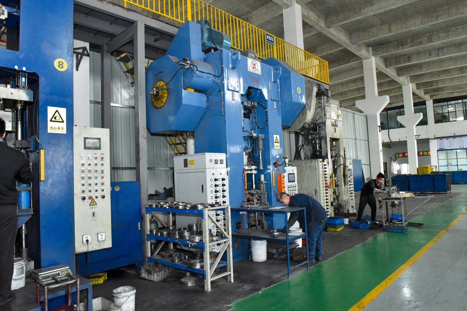
Compaction is also where the press list matters. JH PM runs 19 automatic presses from 6 to 1,000 t; the tonnage in a supplier’s shop, not the process in theory, defines the practical part envelope.
Step 3: Sinter – Where the Strength Is Created
Sintering bonds the particles by solid-state diffusion at 1,120-1,180 °C for iron-based parts – below iron’s 1,538 °C melting point. No melting, no pouring, no solidification structure.
In a hydrogen-nitrogen atmosphere the oxide films on the particle surfaces reduce away, diffusion necks grow between particles, and the pore network shrinks and rounds off. The part densifies slightly – shrinkage of a fraction of a percent for press-and-sinter, against 15-25% for MIM, whose green parts carry binder volume. Continuous pusher furnaces run volume programs; batch furnaces cover prototypes and low volumes.
The step that decides the most, though, is not the peak temperature. Atmosphere dew point, belt speed (time at temperature), and sintering support all shape the result. Two furnaces at the same setpoint do not produce the same part – which is why a supplier’s furnace-control records matter as much as their press list, and why asking for the furnace log behind a failing lot is a reasonable buyer request.
For a deeper walkthrough of this step alone, see What Is Sintering? The Step That Makes PM Parts Strong.
Step 4: Size the Critical Features
Sizing is the tolerance step: a re-press that brings selected features – bores, splines, faces – from IT7-IT9 as-sintered down to IT6-IT7 in one stroke, without chips.
The sizing tool contacts the feature with full-face pressure and corrects a few hundredths of a millimeter of form and size. It only works on parallel, sizeable surfaces (a drafted wall cannot be sized – see the draft angle guide) and only within a few tenths of a millimeter of correction. Features that need IT5 or better go to grinding instead – the economics depend on how many features need that level.
Step 5: Secondary Treatments
Secondary treatment is where the part is matched to its duty – and where porosity becomes either a feature or a problem to close.
- Steam treatment grows Fe₃O₄ inside surface-connected pores: corrosion resistance, plating prep, mild wear faces.
- Plating (zinc, zinc-nickel) requires resin impregnation first on open-pored surfaces, or electrolyte bleeds back out.
- Case hardening / carbonitriding puts HRC 55-62 on wear surfaces while the core stays tough.
- Oil impregnation gives self-lubrication: 12-18% oil by volume in a bushing’s designed 10-25% interconnected porosity.
- Machining covers what pressing cannot form: undercuts, side holes, threads, IT5 faces.
The density and porosity mechanics behind steam treatment and impregnation are covered in the sintered density and porosity guide.
Powder Metallurgy Process Parameters at Each Step
| Step | Typical parameter (iron-based structural PM) | What it sets | Drawing implication |
|---|---|---|---|
| 1. Mix / blend | 20-100 µm powder; 0.5-0.8% lubricant; alloy additions per grade | Alloy composition, blend uniformity | Material spec by MPIF 35 grade, not generic “iron” |
| 2. Compact | 400-600 MPa; green density 6.4-7.2 g/cm³ (85-92% of wrought) | Geometry, density, all as-pressed features | Keep walls parallel to press stroke; draft only on punch-cavity features |
| 3. Sinter | 1,120-1,180 °C, H₂-N₂ atmosphere; shrinkage a fraction of a % (press-and-sinter) | Strength, pore structure, dimensional change | Flatness and distortion depend on support and density balance, not temperature alone |
| 4. Size | One-stroke re-press on selected features | IT6-IT7 on bores, splines, faces | Reserve for genuinely critical dimensions; parallel walls only |
| 5. Secondary | Steam, plating (+impregnation), case hardening, oil, machining | Corrosion, wear, lubrication, final accuracy | Specify the function (e.g. “plating-ready”), let DFM pick the route |
Values in the table are Industry Reference ranges for conventional press-and-sinter ferrous PM (Category A); the “at JH PM” figures are Supplier Capability (Category C) – our current press and furnace list. Actual numbers for a specific part are alloy-, geometry- and process-specific, and get confirmed per feature in the DFM note.
FAQ – How Does Powder Metallurgy Work?
Now You Know the Process. Send the Part and We’ll Map It Onto These Steps.
Upload your drawing (STEP or PDF) with part weight, annual volume, material or target grade, critical tolerances and the load case. Within 48 hours you get a written DFM note mapping your part onto this process: powder grade, compaction direction, which features size and which machine, density target, and secondary treatments – priced per option. JH PM: IATF 16949, 19 presses from 6 to 1,000 t, 10 sintering furnaces, tooling built in-house.
Engineering References
- MPIF: Making Metal Powder (atomization, reduction, electrolysis, chemical)
- MPIF Standard 35 – Materials Standards for PM Structural Parts
- ASTM B962 – Density of Compacted or Sintered PM Products
- ISO 286 – IT tolerance grades referenced throughout
- ASM Handbook, Volume 7 – Powder Metallurgy
- JH PM internal production data (press tonnage, furnace profiles, tooling lead times), September 2026
Numbers marked “at JH PM” are first-hand production references; ranges marked “commonly” or “typically” are industry references that vary by alloy, geometry and supplier.