- Key Takeaways
- Metal injection molding (MIM) is a powder metallurgy process that injection-molds a mix of fine metal powder and thermoplastic binder, then removes the binder and sinters the part to 95–98% density.
- The MIM process has four steps: feedstock preparation, injection molding, debinding, and sintering.
- MIM suits small, complex parts under 100 g (sweet spot 1–50 g) — undercuts, internal threads, and thin walls down to 0.5 mm are moldable.
- As-sintered tolerances are typically ±0.05 mm (±0.3%); the part shrinks 15–20% during sintering, which is compensated in the mold design.
- MIM tooling costs $5,000–$20,000 (industry typical) and takes 4–8 weeks; the process pays off from roughly 5,000+ parts per year.
- MIM parts reach 95–98% density with mechanical properties approaching wrought material — far denser than press-and-sinter PM (85–92% as-sintered).
What Is Metal Injection Molding?
Definition — metal injection molding (MIM): a powder metallurgy process that mixes fine metal powder (5–20 μm) with a thermoplastic binder, injection-molds the mixture like plastic, then debinds and sinters it into dense solid parts. MIM suits complex parts under 100 g (sweet spot 1–50 g) at volumes of 5,000+ per year, holds ±0.05 mm (±0.3%) tolerances, and reaches 95–98% density. Its four steps: feedstock preparation, injection molding, debinding, and sintering. (Industry-typical values; MPIF-aligned.)
Metal injection molding (MIM) is a metal-forming process that manufactures small, complex parts by injection-molding a blend of fine metal powder and thermoplastic binder — exactly like plastic injection molding — and then removing the binder and sintering the part into a dense solid component.
Think of MIM as plastic injection molding’s metal counterpart. The binder gives the metal powder the flowability of plastic, so the molding stage carries the full geometric freedom of plastic parts: undercuts, internal threads, cross-holes, thin walls, and 3D complexity that no die-pressing or casting process can match at volume. After debinding and sintering, what remains is 95–98% dense metal with mechanical properties approaching wrought material.
MIM is technically a branch of powder metallurgy, but the two processes serve different jobs.
MIM vs. Powder Metallurgy: What’s the Difference?
Metal injection molding (MIM) mixes fine powder (5–20 μm) with binder and injects it under relatively low pressure — suited to small, intricate parts (typically under 100 g) at 5,000–100,000+ volumes, reaching 95–98% density.
Conventional powder metallurgy (PM, press-and-sinter) compacts coarser powder uniaxially in a rigid die at 200–700 MPa, then sinters — suited to larger, simpler geometries (up to ~75 mm) at very high volumes, typically 85–92% density as-sintered.
Both processes, along with die casting, are complementary tools — a good manufacturing partner helps you choose between them part by part.
How Does the Metal Injection Molding Process Work?
The MIM process consists of four main stages — feedstock preparation, injection molding, debinding, and sintering — followed by optional secondary operations such as machining, heat treatment, and surface finishing.
Process image: images/mim-process-flow.png — Alt text: “Metal injection molding process flow: feedstock preparation, injection molding, debinding, sintering, secondary operations”
Step 1: Feedstock Preparation
Fine spherical metal powder — typically 5–20 μm particle size — is blended with a multi-component thermoplastic binder system (commonly paraffin wax, polyethylene or polypropylene, and stearic acid). The binder makes up 30–50% of the feedstock by volume; the remainder is metal.
The mixture is compounded in a heated sigma-blade mixer or twin-screw extruder until perfectly homogeneous, then pelletized into granules. Feedstock homogeneity is critical: inconsistent powder loading is the leading cause of warpage and density variation downstream.
Step 2: Injection Molding
The pelletized feedstock is heated to 150–220°C and injected into a steel mold cavity under 80–200 MPa — nearly identical to plastic injection molding, often on the same class of machines.
The result is a “green part”: it has the full final geometry, but contains both powder and binder, and is intentionally molded 15–20% oversized in every dimension. That oversizing compensates for the shrinkage that comes later in sintering.
Step 3: Debinding
The green part enters debinding, where most of the binder (60–90%) is removed, leaving a fragile, porous “brown part” held together by residual binder and powder particle contact. The three industrial methods:
- Solvent debinding — immersion in a solvent (water or heptane) dissolves the wax fraction; 4–24 hours. Most common and versatile.
- Catalytic debinding — acid vapor breaks down polyacetal-based binders at 110–130°C; 2–6 hours. Fastest, suited to high volume.
- Thermal debinding — slow furnace heating to 200–600°C decomposes the binder; 12–48 hours. Simple parts, thicker walls.
Debinding is the MIM bottleneck: binder removal proceeds at roughly 2–3 mm of wall thickness per hour, which is why very thick sections are impractical.
Green-to-sintered image: images/mim-green-to-sintered.png — Alt text: “MIM part transformation from oversized green part to brown part after debinding to final dense sintered component”
Step 4: Sintering
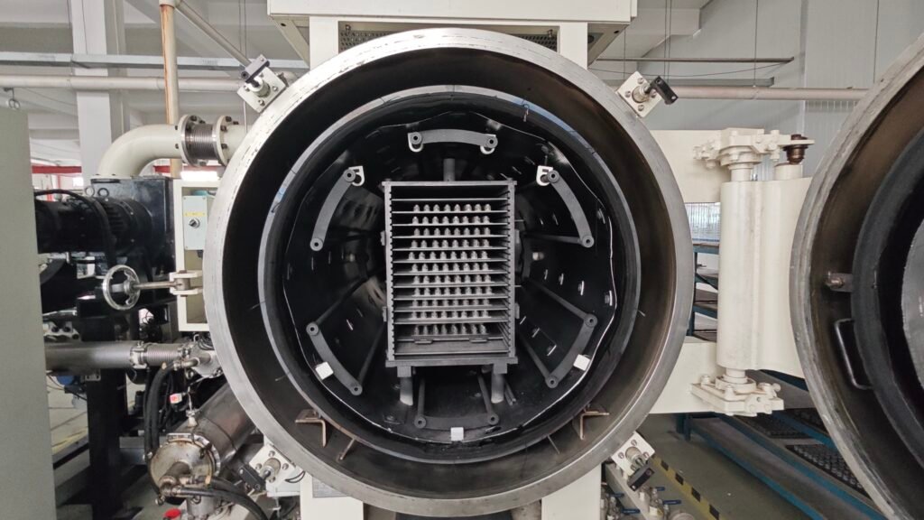
The brown part is sintered in a controlled atmosphere (hydrogen, nitrogen, argon, or vacuum) at 1,100–1,450°C — near but below the alloy’s melting point.
During sintering the metal particles diffusion-bond and densify: the part shrinks 15–20% linearly and consolidates to 95–98% of theoretical density, emerging with mechanical properties comparable to wrought metal. Because the shrinkage is isotropic and highly predictable, the mold cavity is designed oversized to hit final dimensions.
Step 5: Secondary Operations (Optional)
Many MIM parts ship as-sintered. Where required, secondary operations include:
- Machining — critical tolerances beyond ±0.05 mm on selected features
- Heat treatment — hardening, tempering, aging (17-4PH age hardening is common)
- Surface finishing — tumble polishing, electropolishing, plating, PVD coating
- Tumbling/vibratory finishing — deburring and cosmetic surfaces
What Materials Can Be Used in Metal Injection Molding?
The most common MIM materials are stainless steels 316L and 17-4PH, followed by low-alloy steels, soft magnetic alloys, cobalt-chromium, titanium alloys, and tungsten heavy alloys.
| Material | Typical use | Notes |
|---|---|---|
| 316L stainless | Medical devices, marine, corrosion-resistant parts | Biocompatible; dominant in medical/dental; ~485 MPa UTS as-sintered |
| 17-4PH stainless | High-strength structural parts, aerospace, firearms | Age-hardenable (H900) to ~1,100 MPa UTS; ~900 MPa as-sintered |
| Low-alloy steels (Fe-Ni, Fe-Cr) | Automotive, firearms, industrial | Cost-effective structural workhorse |
| Soft magnetic alloys (Fe-50Ni, Fe-3Si) | Sensors, electromagnetic components, motors | Optimized magnetic performance |
| Co-Cr (F75) | Implants, wear-resistant instruments | 99% density achievable |
| Ti-6Al-4V | Aerospace, medical lightweight parts | Higher cost, demanding process control |
| Tungsten heavy alloys | Counterweights, radiation shielding | Vibration damping, high density |
Values are typical industry ranges for material selection guidance, not guaranteed specifications — always confirm against your specific drawing.
What Are the Advantages of Metal Injection Molding?
The main advantages of MIM are unmatched geometry complexity in small parts, near-wrought mechanical properties at 95–98% density, 95%+ material utilization, low unit cost at volume ($0.50–3 per part, industry typical), and the ability to consolidate multi-part assemblies into single components.
1. Geometry Freedom No Other Metal Process Matches
Because the shaping happens in a plastic-like injection step, MIM molds undercuts, internal threads, cross-drilled holes, and thin walls (down to 0.5 mm) that would require expensive 5-axis machining or are simply impossible in die-pressing. Internal threads form directly on collapsible cores; through-holes down to 0.5 mm are routine.
2. Near-Wrought Properties
At 95–98% density, MIM parts carry mechanical properties close to wrought material — markedly stronger than die castings and far denser than press-and-sinter PM parts. MIM 316L reaches ~485 MPa UTS at 98% density; 17-4PH exceeds 1,100 MPa after age hardening (H900).
3. Material Efficiency
MIM is a near-net-shape process with 95%+ material utilization (industry typical) — slightly below press-and-sinter PM’s 97%+, because runner and gate material cannot always be fully reclaimed. That efficiency is decisive when the material is titanium, cobalt-chrome, or tungsten, where chips from machining are expensive waste.
4. Low Unit Cost at Volume
Once tooling is amortized, small complex MIM parts typically cost $0.50–3 each (industry typical) — often a fraction of the CNC-machined equivalent. Injection cycle times of 30–90 seconds per shot keep output high, and well-maintained tools routinely run 1–2 million cycles.
5. Part Consolidation
Multiple machined or stamped components can often be redesigned as one molded part — eliminating assembly cost, fastener inventory, and joint failure points.
What Are the Limitations of Metal Injection Molding?
The main limitations of MIM are part size (economically practical under 100 g), wall thickness (0.5–10 mm, core out thicker sections), high upfront tooling ($15k–50k, 4–8 weeks), a long qualification timeline (8–12 weeks to first articles), and tolerance limits of ±0.05 mm as-sintered.
- Size ceiling: The economic sweet spot is 1–50 g; parts up to ~100 g are routine, and ~400 g is possible but rare. Larger parts face impractical debinding times and sintering distortion — investment casting takes over above that.
- Wall thickness window: 0.5–6.0 mm is ideal; sections above ~10 mm must be cored out, because binder removal through thick sections is inherently slow.
- Upfront tooling cost: MIM molds cost $15,000–50,000 (industry typical) depending on complexity and cavity count; side-actions for undercuts add $3,000–8,000 each. Below ~5,000 parts per year, CNC machining usually wins on total cost.
- Long program timeline: Tool build 4–8 weeks, plus sampling, debinding, and sintering validation: plan on 8–12 weeks from kickoff to first qualified articles.
- Tolerance ceiling: As-sintered ±0.05 mm (±0.3%) is standard; tighter features need secondary machining. The 15–20% sintering shrinkage must be characterized per material — dimensional consistency depends on it.
- Cosmetic surfaces: As-sintered finish is Ra 0.8–1.6 μm — fine for function, but cosmetic parts need tumble polishing, electropolishing, or PVD.
Metal Injection Molding vs. Machining, Casting, and PM: Which Should You Choose?
Choose MIM for 5,000–100,000+ annual volumes of small, intricate parts under 100 g; choose CNC machining for prototypes and ultra-tight tolerances; choose die casting for larger thin-wall aluminum housings; choose press-and-sinter PM for simpler geometries at very high volumes.
| Factor | MIM | CNC Machining | Die Casting | Powder Metallurgy |
|---|---|---|---|---|
| Best for | Small intricate parts under 100 g | Prototypes and ultra-tight tolerances | Large thin-wall aluminum or zinc housings | High-volume gears, bushings, cams, sprockets |
| Best volume | 5,000 – 100,000+ pcs | 1 – 1,000 pcs | 10,000+ pcs | 10,000+ pcs |
| Typical part size | Small (<100 g, sweet spot 1–50 g) | Nearly unlimited | Medium to large | Up to ~75 mm |
| Material utilization | 95%+ | 30–60% | 80–95% | 97%+ |
| Typical tolerance (as-made) | ±0.05 mm (±0.3%) | ±0.005–0.025 mm | ±0.1–0.2 mm | ±0.1 mm industry-typical |
| Density | 95–98% | 100% (wrought) | ~98–100% | 85–92% as-sintered |
| Geometry complexity | Very high | High (with cost) | Moderate (draft required) | Moderate (pressable) |
| Tooling cost | High ($5k–20k) | None | High ($1k–5k) | Medium ($5k–20k) |
| Unit cost at high volume | Low ($0.50–3) | High ($8–40) | Low ($1–5) | Very low ($0.30–2) |
The practical rule of thumb:
- Choose MIM when the part is small, geometrically complex (undercuts, threads, cross-holes), and needed at 5,000+ volumes.
- Choose machining for prototypes, low volumes, or tolerances tighter than ±0.05 mm.
- Choose die casting for larger aluminum or zinc housings where MIM’s size ceiling binds.
- Choose press-and-sinter PM for simpler, larger parts at very high volumes where unit cost is king.
How Do You Design Parts for Metal Injection Molding?
To design for MIM: keep wall thickness uniform at 0.5–6 mm, core out sections above 10 mm, add 0.5–2° draft, avoid sharp internal corners, and involve your MIM supplier before the mold is cut — early DFM feedback can cut part cost by 20–40%.
- Design like plastic injection molding: Draft angles of 0.5–2°, generous radii, and uniform walls.
- Respect the wall thickness window: 0.5–6.0 mm is the sweet spot. Sections above ~10 mm must be cored out.
- Tolerance only what matters: Let general features live within ±0.05 mm as-sintered; reserve machining for critical dimensions.
- Consolidate assemblies: Replace two or three machined parts plus fasteners with one molding.
- Involve your MIM supplier early: Gate location, shrinkage characterization, and moldability review before tooling commitment.
What Is Metal Injection Molding Used For?
MIM is used most heavily in medical and dental devices, consumer electronics, and firearms, followed by automotive, aerospace, and industrial hardware — anywhere small, complex metal parts are needed at volume.
Applications image: images/mim-applications.png — Alt text: “Metal injection molding applications: surgical instruments, orthodontic brackets, watch cases, firearm components, and electronic hinges”
- Medical and dental: Surgical instruments, laparoscopic components, orthodontic brackets, bone screws.
- Consumer electronics: Hinge mechanisms, watch cases, SIM trays, camera brackets at 100M+ annual volumes.
- Firearms: Triggers, hammers, sears, sights, safety levers.
- Automotive: Turbocharger vanes, fuel-system components, shift forks, sensor housings.
- Aerospace and defense: Latching systems, lightweight titanium and superalloy components.
- Industrial hardware: Locking mechanisms, valve bodies, textile machinery parts.
When Is Metal Injection Molding the Right Choice?
MIM is likely your best option when:
- Annual volume is 5,000 parts or more
- The part weighs 100 g or less (ideally 1–50 g)
- The geometry features undercuts, internal threads, or cross-holes
- Tight tolerances are needed on only a few critical dimensions
- The material is expensive (titanium, Co-Cr, tungsten) and near-net-shape saves money
- Multiple machined parts could be consolidated into one component
- The program timeline allows 8–12 weeks to first articles
What to Look for in a MIM Supplier
When choosing a metal injection molding supplier, verify five capabilities: IATF 16949 (or ISO 9001 baseline) certification, in-house control of molding, debinding, and sintering, a proven material library for your alloy, PPAP documentation and lot traceability, and CMM-based inspection with SPC on critical dimensions.
- Certification: IATF 16949 for automotive programs; ISO 13485 for medical devices.
- Integrated process control: In-house debinding and sintering for fast feedback loops.
- Material experience: Request property data on your exact alloy from production runs.
- Quality documentation: PPAP submissions and full lot traceability.
- Unbiased process selection: Partners who offer MIM, PM, and die casting side by side.
Get a MIM Feasibility Check on Your Drawing
The fastest way to know whether metal injection molding works for your part is to have it reviewed by engineers who run MIM, press-and-sinter PM, and die casting side by side — and who will tell you straight when a different process is the better fit.
Send your drawings and annual volumes to JH PM — email us directly, or use the RFQ form and attach your 3D file (STEP or IGES). Our engineers will review the geometry, confirm the right process, and return a cost comparison — including an honest break-even analysis against machining — within 48 hours.
FAQ: Metal Injection Molding Questions Answered
What is the difference between MIM and powder metallurgy?
Metal injection molding (MIM) mixes fine powder with binder and injects it like plastic — suited to small, complex parts under 100 g at 95–98% density. Conventional powder metallurgy (press-and-sinter) compacts powder uniaxially in a rigid die — suited to larger, simpler parts up to ~75 mm at very high volumes, typically 85–92% density as-sintered.
What materials can be used in metal injection molding?
The most common are stainless steels 316L and 17-4PH, low-alloy steels, and soft magnetic alloys. Cobalt-chromium (implants), titanium Ti-6Al-4V, tungsten heavy alloys, and tool steels are also commercially established.
How tight can MIM tolerances be?
As-sintered, expect ±0.05 mm (±0.3% of dimension, industry typical). Tighter tolerances on selected critical features are achievable with secondary machining. Sintering shrinkage of 15–20% is predictable and compensated in the mold design.
What is the minimum production volume for MIM?
As a rule of thumb (industry typical), 5,000 parts per year for complex geometries; the crossover against machining can reach 20,000 for simpler shapes. Below that, tooling amortization usually favors CNC machining.
How much does MIM tooling cost?
Typical MIM tooling costs $5,000–20,000 depending on complexity and cavity count, with side-actions for undercuts adding $1,000–3,000 each. Tool build takes 4 weeks; plan on 6-8 weeks from kickoff to first qualified articles.
What is the maximum part size for MIM?
The economic sweet spot is 1–50 g; parts up to 100 g are routine and ~400 g is possible. Larger parts face long debinding times and sintering distortion — above that range, investment casting is usually the better process.
Is MIM as strong as machined metal?
Nearly. MIM parts reach 95–98% of theoretical density with mechanical properties approaching wrought material — for example, MIM 17-4PH exceeds 1,100 MPa UTS after age hardening (H900). Fatigue-critical applications should still be verified against your specific loading conditions.
What certifications should a MIM supplier have?
Look for ISO 9001 as a baseline, IATF 16949 for automotive work, and ISO 13485 for medical devices. Beyond certificates, verify PPAP documentation capability, lot traceability, CMM-based inspection, and in-house control of debinding and sintering.
“`html “`