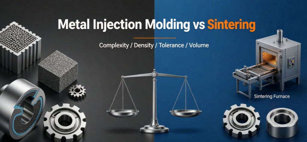
Metal Injection Molding vs. Sintering: MIM vs. Press-and-Sinter PM
A technical decision framework comparing two manufacturing routes that share a sintering stage but differ fundamentally in geometry capability, tooling complexity, density, and break-even economics.
- MIM injection-molds fine metal powder bound in thermoplastic, achieving complex 3D geometries, cross-holes, and thin walls at high density (≥95% theoretical) but with higher tooling cost and significant shrinkage (12 to 18%).
- Press-and-Sinter PM uniaxially compacts coarser powders in rigid dies at 1 to 3 seconds per stroke, producing multi-level axial profiles at lower tooling cost and higher throughput, but cannot form features perpendicular to the pressing direction without secondary CNC.
- Selection Rule: If the part has undercuts, cross-holes, or thin walls under 100 g, evaluate MIM. If the part is an axial profile (gear, bushing, bracket) above 2,000 pcs/year, press-and-sinter PM is typically more economical.
Key Takeaways
- Shared Sintering, Divergent Forming: Both MIM and PM culminate in sintering, but green part formation differs entirely: fluid injection vs. cold uniaxial compaction.
- Density vs. Functionality: MIM targets near-full density. PM retains controlled porosity that can be functional (self-lubricating bearings) or sealed via resin impregnation.
- Tooling Cost vs. Geometry Complexity: MIM molds ($10,000 to $50,000+) manage multi-cavity runners, slides, and shrinkage compensation. PM dies ($1,500 to $8,000) are punch-and-die assemblies for axial ejection.
- Break-Even Depends on Secondary Operations: When a PM blank requires extensive post-sinter CNC machining to create cross-holes or undercuts, MIM’s net-shape advantage may offset its higher per-piece cost.
Shared Foundation: Both Are Powder Metallurgy
Both metal injection molding and conventional press-and-sinter are recognized branches of powder metallurgy. They share a fundamental principle: metal powders are consolidated below the base metal melting point through solid-state atomic diffusion during sintering. The divergence occurs at the green-forming stage, where the unfired geometry is created:
- MIM Green Forming: Fine gas-atomized powders (<20 µm) are compounded with 30% to 40% volume fraction of thermoplastic binders (wax, polyethylene, polyacetal). The resulting feedstock is injection-molded under heat and pressure into complex 3D tool cavities.
- PM Green Forming: Coarser water-atomized or sponge-iron powders (50 to 150 µm) are blended with less than 1% solid organic lubricants (zinc stearate) and compacted at 400 to 800 MPa inside rigid carbide dies by uniaxial punches.
After forming, both routes converge on thermal sintering in controlled-atmosphere furnaces to achieve metallurgical bond strength. The key engineering difference: MIM must first undergo debinding (thermal or solvent removal of the binder system) before the sintering stage, adding process time and capital cost.
MIM vs. Press-and-Sinter: Process Step Comparison
The manufacturing sequence for each route determines cycle time, capital equipment, and in-process quality risks:
| Process Step | Metal Injection Molding (MIM) | Press-and-Sinter PM |
|---|---|---|
| 1. Feedstock | Fine powders (<20 µm) + 30 to 40% vol thermoplastic binder system | Coarse powders (50 to 150 µm) + <1% solid lubricant |
| 2. Green Forming | Injection molding at 150 to 200°C under 50 to 150 MPa injection pressure | Uniaxial die compaction at 400 to 800 MPa, 1 to 3 s cycle |
| 3. Debinding | Thermal or solvent removal of binder (6 to 24 h); shrinkage begins | Not required (lubricant burns off during early sintering) |
| 4. Sintering | High-temperature vacuum or hydrogen (1,250 to 1,400°C); 12 to 18% volumetric shrinkage | Continuous mesh-belt (1,120 to 1,180°C); minimal dimensional change |
| 5. Secondary Ops | Minimal: usually sizing, plating, or heat treat only | Sizing, CNC cross-holes, oil impregnation, steam treatment, plating |
| Typical Cycle | Days (debinding + sintering batch) | Hours (continuous belt through furnace) |
Geometry Capabilities and Constraints
The most important selection criterion is part geometry. Each forming method imposes hard physical constraints on what can be produced as-formed:
Press-and-Sinter PM: Axial Ejection Dictates Design
Conventional PM compacts powder inside a rigid die using upper and lower punches that move along a single vertical axis. The green part must clear the die cavity during ejection without lateral interference. This means:
- Feasible: Multi-level stepped faces, gear teeth, splines, keyways, flanges, holes parallel to pressing direction, and complex profiles in the radial die-controlled plane.
- Not Feasible as-Formed: Cross-drilled holes perpendicular to the pressing axis, internal undercuts, re-entrant features, radial grooves, threads, and lateral holes. These require secondary CNC machining after sintering.
MIM: 3D Freedom with Shrinkage Compensation
MIM feedstock flows like molten plastic, filling complex 3D mold cavities with undercuts, cross-holes, thin walls, and internal features using side slides and lifters. The primary geometric constraints are:
- Shrinkage Compensation: The 12 to 18% volumetric shrinkage during debinding and sintering must be precisely scaled in the mold design. Tooling requires extensive simulation and iteration to achieve final dimensional accuracy.
- Part Mass Limit: Economic production limits MIM to parts typically under 100 grams. Larger parts require excessive binder volume and disproportionate sintering times.
- Wall Thickness: Walls below 0.5 mm risk incomplete feedstock filling; walls above 8 to 10 mm cause extended debinding cycles and risk internal defects.
Density, Porosity, and Mechanical Properties
Density is the primary differentiator for mechanical performance between the two routes:
| Property | MIM | Press-and-Sinter PM |
|---|---|---|
| Typical Density | 95 to 98% theoretical (≥7.6 g/cm³ for Fe alloys) | 80 to 92% theoretical (6.4 to 7.4 g/cm³ for Fe alloys) |
| Porosity | Isolated, closed pores; not interconnected | Open, interconnected pores (can be functional for oil retention) |
| Tensile Strength (Fe alloys) | Comparable to wrought (500 to 1,200 MPa depending on alloy and heat treat) | Lower than wrought (250 to 800 MPa); density-dependent |
| Impact Toughness | Higher (near-wrought due to high density) | Lower (residual porosity concentrates stress) |
| Self-Lubricating | Not possible (closed porosity) | Yes, via 18 to 25% open porosity + vacuum oil impregnation |
| Corrosion Resistance | High density minimizes differential aeration cells | Open pores risk fluid entrapment; requires sealing for wet service |
Tooling Cost and Complexity
Tooling investment represents the largest upfront cost difference between the two processes:
| Factor | MIM Mold | PM Die Set |
|---|---|---|
| Typical Cost | $10,000 to $50,000+ (multi-cavity with slides) | $1,500 to $8,000 (standard multi-punch assembly) |
| Design Complexity | Runners, gates, thermal management, shrinkage scaling, side slides, lifters | Vertical punch kinematics, core rods, carbide inserts |
| Lead Time | 6 to 12 weeks (design iteration + sampling) | 3 to 5 weeks (JH PM: 20 working days standard) |
| Design Changes | Difficult and expensive (steel mold modification) | Moderate (punch/die insert replacement or wire-EDM) |
| Cavities | 2 to 8+ cavities typical (runner system required) | 1 cavity standard; multi-cavity possible for small parts |
| Tool Life | 100,000+ shots (hardened steel) | 500,000+ strokes (carbide inserts in tool steel bodies) |
Break-Even Cost Model
The total program cost for each route follows a standard cost structure. The break-even volume determines which process delivers lower total cost:
Total Program Cost
$$C_{\text{total}} = C_{\text{tooling}} + Q \times \left( C_{\text{material}} + C_{\text{processing}} + C_{\text{secondary}} \right)$$Break-Even Volume (MIM vs. PM + Secondary CNC)
$$Q_{BE} = \frac{C_{\text{tooling, MIM}} – C_{\text{tooling, PM}}}{C_{\text{unit, PM+CNC}} – C_{\text{unit, MIM}}}$$Where $C_{\text{unit, PM+CNC}}$ represents the per-piece cost of a press-and-sinter blank plus all secondary CNC operations required to achieve the final geometry. If MIM produces the geometry net-shape without secondary machining, and the CNC cost on the PM route is substantial, the denominator grows and the break-even volume drops, favoring MIM.
General economic guidance:
- Simple axial parts (gears, bushings, brackets): Press-and-sinter PM is almost always lower cost at any volume.
- Complex 3D parts with cross-holes and undercuts: MIM becomes competitive when the PM route requires 3 or more secondary CNC setups per part.
- Low-volume prototypes (<500 pcs): CNC machining from bar stock avoids tooling entirely for both routes.
Engineering Decision Matrix
The following matrix summarizes the key selection criteria for sourcing engineers:
| Decision Factor | MIM | Press-and-Sinter PM |
|---|---|---|
| Part Geometry | Complex 3D: undercuts, cross-holes, thin walls, internal features | Axial profiles: steps, splines, gears, bushings, brackets |
| Part Mass | <100 g typical; <250 g maximum | 1 g to >500 g; limited by press tonnage |
| Required Density | ≥95% theoretical (near-wrought properties) | 80 to 92% theoretical (functional porosity possible) |
| Dimensional Tolerance | ±0.3% to ±0.5% of dimension (shrinkage variability) | ±0.05 mm as-sintered; ±0.025 mm sized (radial) |
| Tooling Investment | High ($10,000 to $50,000+) | Moderate ($1,500 to $8,000) |
| Production Volume | ≥5,000 pcs/year typical for tooling amortization | ≥2,000 pcs/batch (JH PM MOQ) |
| Cycle Time | Days (batch debinding + sintering) | Hours (continuous belt, 1 to 3 s compaction) |
| Self-Lubricating | Not possible | Native capability (open porosity + oil impregnation) |
| Secondary CNC Required | Minimal (net-shape or near-net-shape) | Required for cross-holes, threads, lateral undercuts |
When to Choose MIM
MIM is the appropriate forming route when the following conditions are met:
- Complex 3D Geometry: Parts with undercuts, cross-drilled holes, internal threads, thin walls, or re-entrant features that cannot be ejected from a rigid uniaxial die.
- Small Part Mass: Components under 100 grams where the volume of MIM feedstock and debinding time remain economical.
- High Density Required: Applications demanding near-wrought mechanical properties (tensile strength, impact toughness, fatigue life) that cannot be achieved with as-sintered PM densities.
- Net-Shape Economics: When the total cost of a PM blank plus multiple CNC secondary operations exceeds the MIM per-piece cost at production volume.
- Stainless Steel Micro-Components: MIM excels at producing 316L and 17-4PH stainless steel parts for medical instruments, firearms, and consumer electronics where high density and corrosion resistance are required simultaneously.
For MIM-specific capabilities and portfolio examples, see JH MIM’s MIM vs. Sintering guide.
When to Choose Press-and-Sinter PM
Conventional press-and-sinter PM is the correct route for the majority of high-volume structural metal components:
- Axial Geometry: Parts designed with features along the pressing direction: stepped hubs, splines, gear teeth, flanged bushings, and mounting brackets.
- High-Volume Production: Cycle rates of 1 to 3 seconds per stroke make PM the most productive net-shape forming process for metal parts above 2,000 pieces per batch.
- Self-Lubricating Bearings: The controlled interconnected porosity unique to press-and-sinter PM cannot be replicated by MIM, casting, or forging.
- Tight Radial Tolerances: Sized PM components hold ±0.025 mm on critical bore and outer diameters, tighter than typical MIM shrinkage tolerance bands.
- Lower Tooling Cost: When the part geometry does not require MIM’s 3D capability, PM die sets cost 5 to 10 times less than MIM molds and deliver in half the lead time.
- Large Cross-Sections: PM presses up to 1,000 tons can compact parts with projected areas exceeding 150 mm, far beyond MIM’s practical mass limits.
JH PM Press-and-Sinter Capabilities
Located in Shaoxing, Zhejiang, JH PM (Ningbo Jiehuang Chiyang Electronic Tech) manufactures custom press-and-sinter structural components under automotive-grade quality systems:
- Factory Scale: 7,000 m² manufacturing plant operating 19 automated mechanical and hydraulic PM compaction presses ranging from 6 to 1,000 tons.
- Thermal Capacity: 2 continuous mesh-belt protective atmosphere sintering furnaces and vacuum sintering units with real-time dew-point monitoring, delivering over 3,000 metric tons annually.
- Metrology Lab: 3 German Zeiss CMMs, 1 dedicated CNC gear measuring center, Archimedes density balances, and optical metallographic analyzers.
- Quality Registrations: Dual-certified to IATF 16949:2016 and ISO 9001:2015 with full MES barcode lot traceability.
- Commercial Agility: MOQ begins at 2,000 pieces. Tooling lead time 20 working days; T0 trial samples within 25 working days; DFM reviews within 48 hours.
- Scope Boundary: Non-implantable surgical device hardware, diagnostic instruments, and industrial components only (explicitly NO ISO 13485).
For MIM capabilities within the same corporate group, visit JH MIM.
Frequently Asked Questions
Not Sure Whether Your Part Fits MIM or Press-and-Sinter?
Send your 2D drawings and 3D CAD models to JH PM’s engineering team. We will evaluate geometry, volume, and tolerance requirements against both manufacturing routes and deliver a process recommendation with tiered pricing within 48 hours.