- Blog
- Materials
- PM Tooling Cost: US vs Europe vs China Price Guide
- Powder Metallurgy
- Process
- Products
- Quality
- Sintered metal parts
- Sintered parts
- Blog
- Materials
- PM Tooling Cost: US vs Europe vs China Price Guide
- Powder Metallurgy
- Process
- Products
- Quality
- Sintered metal parts
- Sintered parts
Powder Metallurgy Gears: Design, Tolerances & Sintering Guide
An engineering guide to powder metallurgy gears: managing DIN and AGMA accuracy classes, fatigue dynamics in porous root fillets, helical tooling kinematics, and dedicated metrology verification.
- Achievable Accuracy: DIN 8 to 9 (AGMA 8 to 9) as-sintered; secondary sizing achieves DIN 7 to 8 on tooth profiles without hobbing.
- Structural Fatigue Resistance: Root bending strength and tooth flank pitting resistance scale with sintered density (typically 6.8 to 7.3 g/cm³) and alloy selection (MPIF FC-0208, FLN2-4405).
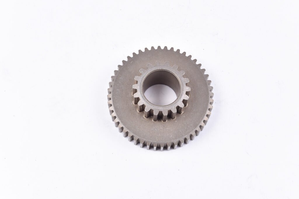
- Kinematic Forms: Single-stroke pressing produces external spur gears, cluster gears, and internal ring gears; helical gears up to a 30° helix angle are formed using rotating punch systems.
- JH PM Plant Footprint: 19 automated compaction presses (6T to 1,000T), 2 continuous mesh-belt and vacuum furnaces, 3 Zeiss CMMs, and 1 dedicated gear testing instrument under IATF 16949 control.
Involute tooth geometry is generated entirely by the die cavity, delivering >95% material utilization compared to 40 to 60% scrap rates in gear hobbing.
Pores act as microscopic stress risers; elevating core density from 6.8 to 7.2 g/cm³ yields a substantial gain in cyclic root bending fatigue.
Radial features (bore, pitch diameter) hold ±0.025 mm to ±0.05 mm; gear face width (axial height) relies on punch stroke, holding ±0.10 mm to ±0.15 mm.
Calipers and basic probes fail to measure gear tooth lead or involute profile errors ($f_f$, $f_\beta$); inspection requires dedicated gear testing instruments.
Gear Accuracy Classes: What PM Can (and Cannot) Achieve
A frequent error among mechanical designers transitioning from hobbed wrought bar stock to sintered metal is applying universal machining tolerances across all gear features. In press-and-sinter powder metallurgy, dimensional repeatability is anisotropic. Radial tooth profiles copied directly from tungsten carbide die walls achieve high precision, whereas axial thickness varies with punch fill dynamics.
| Processing Route | DIN 3962 | AGMA 2000-A88 | ISO 1328 | Typical Applications |
|---|---|---|---|---|
| As-Sintered | DIN 8 to 9 | AGMA 8 to 9 | Class 8 to 9 | Seat recliners, tailgate actuators, lawn equipment |
| Sized / Repressed | DIN 7 to 8 | AGMA 9 to 10 | Class 7 to 8 | Automotive timing sprockets, oil pump gerotors, power tool drives |
| Surface Rolled / Ground | DIN 6 to 7 | AGMA 11 to 12 | Class 6 to 7 | High-speed automotive transmission pinions, NVH-critical electric drives |
For standard press-and-sinter production, normal module ($m_n$) capability ranges from 0.3 mm to 4.0 mm. Sintering introduces a predictable linear dimensional change between 0.2% and 0.5%, which is compensated in the tooling electrode design.
Fatigue Resistance: Root Bending vs. Flank Pitting
Powder metallurgy gears face two distinct cyclic stress failure mechanisms: root bending fatigue and tooth flank pitting. Managing both requires controlling density and microstructural phase balance.
Root Bending Fatigue
Bending fatigue failure originates at the tooth root trochoid fillet under cyclic cantilever loading. In solid wrought gears, fatigue limits are dictated by surface finish and inclusion cleanliness. In sintered gears, residual pores act as microscopic stress-concentration notches. Increasing density from 6.8 to 7.2 g/cm³ doubles the nominal fatigue endurance limit. To optimize bending fatigue resistance without post-sinter operations, design engineers should specify full-radius root fillets ($R \ge 0.4\text{ mm}$) and pre-alloyed nickel-molybdenum steels.
Flank Contact Fatigue and Pitting
Contact fatigue occurs near the pitch circle where sliding and rolling friction generate intense Hertzian contact stress. When shear stress exceeds the matrix yield strength, subsurface pores collapse, producing micro-pitting and progressive spalling. For heavy-duty drives, gears undergo sinter-hardening (rapid gas quenching inside the furnace cooling zone) or secondary case carburizing, driving particle microhardness to 550 to 700 HV0.1 (equivalent to 52 to 60 HRC).
Gear Configurations & Tooling Kinematics
Powder compaction tooling movements determine which gear architectures can be manufactured near-net-shape.
| Configuration | Tooling Kinematics | Design Envelope |
|---|---|---|
| External Spur Gears | Vertical uniaxial pressing (upper/lower punches) | Straight axial ejection; standard carbide dies achieve >1,000,000 cycles |
| Helical Gears | Punches and core rods rotate synchronously along helix | Helix angle limited to $\beta \le 30^\circ$ (recommended $\le 25^\circ$) for ejection without tooth stripping |
| Cluster / Combination | Independent telescoping multi-level lower punches | Two gears on a single hub in one press cycle, eliminating assembly and welding |
| Internal Ring Gears | Core pin forms internal teeth; outer die forms shell | Eliminates internal shaping or broaching; ideal for planetary gearbox outer rings |
DFM Guidelines for Sintered Gear Design
Designing gears for powder metallurgy requires different geometric rules than designing for gear hobbing or shaper cutting.
- Incorporate tooth tip lands (chamfers): Avoid razor-sharp tooth tips. A flat land or radius of at least
0.25 to 0.40 mmmust be added to the tooth crest. Sharp tool edges chip under 600 MPa compaction pressure, producing burrs during ejection. - Specify full-radius root fillets: Do not use undercut roots or sharp transition corners ($R < 0.3\text{ mm}$). Full-radius trochoids improve powder fill consistency and reduce operational root stress concentrations by up to 30%.
- Integrate web lightening recesses: For gears with pitch diameters exceeding 60 mm, incorporate a recessed central web. Thinning the web reduces required press tonnage and conserves raw alloy powder without compromising gear ring rigidity.
- Maintain uniform wall thicknesses: Ensure the rim thickness below the gear root circle is at least 1.5 to 2.0 times the whole tooth depth ($h_t$). A thin rim over a heavy hub creates neutral-axis density drops during pressing, resulting in cracked roots during sintering.
Metrology & Quality Control for Sintered Gearing
Sintered gear inspection requires dedicated metrology setups. Porous surfaces and minute profile errors cannot be qualified with hand tools.
- Dedicated involute gear testing: Measures total profile error ($F_\alpha$), profile form error ($f_{f\alpha}$), total helix deviation ($F_\beta$), and cumulative pitch error ($F_p$) against DIN 3962 standards.
- Zeiss CMM (3 units): Inspects true position of mounting bores, face runout, keyway perpendicularity, and datum relationships.
- Apparent vs. microindentation hardness (MPIF Standard 51): Macro-Rockwell (HRC) tests collapse surface pores, reading artificially low. True tooth load capacity is verified via micro-Vickers (HV0.1) directly on polished matrix particles.
- Archimedes density profiling (ASTM B962): Sintered gear teeth are sectioned and tested for localized density to verify the root zone meets minimum structural requirements.
Economic Break-Even: PM Gears vs. Hobbed Steel
The economic choice between powder metallurgy and subtractive hobbing balances upfront die costs against recurring per-piece savings.
| Economic Factor | PM Gear | Hobbed / Shaved Steel Gear |
|---|---|---|
| Material utilization | >95% (powder into part shape) | 40 to 60% (chips removed) |
| Production cycle time | 1 to 3 seconds per stroke | 45 to 180 seconds (turning, hobbing, deburring) |
| Initial tooling | $2,000 to $6,000 (carbide die set) | $0 dedicated die (standard fixtures) |
| Acoustic damping (NVH) | Inherent pore structure dampens noise | Solid matrix transmits higher resonance |
| Break-even volume | 2,000 to 5,000 pcs/year | 1 to 1,000 pcs (prototypes, short runs) |
JH PM Gear Manufacturing Capabilities
Located in Shaoxing, China, JH PM manufactures precision sintered structural components, sprockets, and gears for global automotive, power tool, and machinery applications.
| Production footprint | 7,000 m² plant; 3,000+ tons annual sintering capacity |
|---|---|
| Compaction press fleet | 19 precision automatic PM presses (6T to 1,000T), gear diameters up to 120 mm |
| Sintering | 2 industrial furnaces (continuous mesh-belt + high-vacuum), integrated steam oxidation lines |
| Gear inspection | 1 dedicated gear testing instrument, 3 Zeiss CMMs, optical profilometers, 2.5D projectors |
| Quality registrations | IATF 16949:2016, ISO 9001:2015, full MES batch-level traceability |
| MOQ | 2,000 pieces per part number |
| Tooling lead time | 20 working days |
| T0 sample delivery | 25 working days from tooling completion |
| DFM turnaround | 24 to 48 hours |
Get an Engineering DFM Review for Your Gear Program
Send your 2D gear engineering drawings (with normal module, tooth count, pressure angle, and helix angle) and 3D CAD models. Our gear engineers will evaluate tooling kinematics, tolerance classes, and density targets, returning a detailed DFM report within 24 to 48 hours.