Sintering Process Explained: What Actually Happens Inside the Furnace
Most sintering explainers stop at “heat the part below its melting point.” This one goes through the furnace with the part – zone by zone, stage by stage – because that is where strength, dimensions and most hard-to-troubleshoot defects are actually decided.
What Is the Sintering Process, Precisely?
Sintering is a thermal treatment in which powder particles bond by diffusion at a temperature below the metal’s melting point, transforming a loose or pressed powder into a coherent solid with engineered porosity.
That definition carries three claims worth unpacking, because each one has consequences for a part drawing.
First: below the melting point. Iron melts at 1,538 °C; iron-based structural parts sinter at 1,120-1,180 °C. Nothing pours, nothing solidifies, so the pressed geometry survives. A rule of thumb for metals is a sintering temperature around 0.7-0.8 of the absolute melting point – the exact value is alloy-specific.
Second: diffusion does the bonding. At temperature, atoms migrate across particle contacts and necks grow where particles touch. The part never passes through a liquid phase in conventional press-and-sinter PM – so there is no solidification structure, no casting porosity in the metallurgical sense, and no grain refinement from a melt. What you get is a different microstructure entirely: particles that have grown into each other around a designed pore network.
Third: the shape was already finished before the furnace. Sintering changes strength and slightly changes dimensions; it does not change geometry. If a feature is wrong on the green compact, the furnace will faithfully preserve that wrongness. This is why compaction – not sintering – is the geometry step, and why a dimensional problem that appears “after sintering” often needs to be diagnosed one step upstream.
New to the topic entirely? Start with the intro explainer, What Is Sintering? The Step That Makes PM Parts Strong, then come back for the furnace-level view.
The Physics in Three Stages
Within the hot zone, sintering proceeds through three overlapping stages: neck formation and growth, pore rounding, and densification. The boundaries overlap in practice, but the stages are a useful mental model because each one is driven by a different mechanism and each one leaves its fingerprint on the part.
Stage 1: Neck formation and growth
Where particles touch, diffusion starts building a bridge – a neck. Neck growth is fastest early: most of the strength gain happens here, at nearly constant density. This is why a freshly sintered part can pass a strength check yet still look “porous” under the microscope. The part has not densified much yet; it has simply become one piece.
Stage 2: Pore rounding
Sharp, angular pores have more surface energy than round ones, and surface energy is what sintering spends. Pores smooth out and begin to isolate. Small pores shrink faster than large ones – which is why powder particle size distribution matters: a wide distribution leaves coarse pores that stage 3 cannot fully close.
Stage 3: Densification
Pores shrink toward closed porosity and the part contracts. In press-and-sinter ferrous PM this shows up as the fraction-of-a-percent shrinkage the tooling was sized for; pushing further – toward 95%+ density – costs exponentially longer cycles or special routes (warm compaction, double press-double sinter, infiltration), each priced separately.
Where the process lands depends on the levers: temperature, time at temperature, powder chemistry and particle size, green density, and atmosphere. There is no single universal sintering recipe; two suppliers with identical furnace setpoints can ship different parts, which is the practical reason furnace records matter more than furnace specifications.
Inside the Furnace: The Four Zones
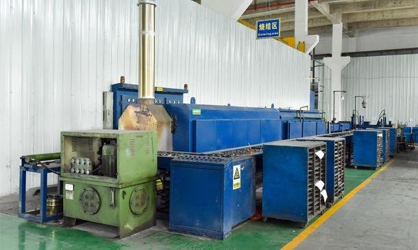
A continuous sintering furnace is not one hot box – it is a controlled sequence, and each zone exists because skipping or rushing it produces a specific, recognizable defect.
| Zone | Typical condition (iron-based PM) | What it does | If it goes wrong |
|---|---|---|---|
| 1. Delubrication | ~400-650 °C, oxidizing carrier | Burns out the 0.5-0.8% pressing lubricant slowly enough to avoid blistering | Rushed: lubricant cracks inside the part → carbon pickup, blistering, soot |
| 2. Preheat | Ramp to near-sintering temp | Brings the part uniformly to temperature; equalizes thermal gradients | Thermal shock and distortion on thin or thick-thin sections |
| 3. Hot zone (sintering) | 1,120-1,180 °C, H₂-N₂ atmosphere | Necks grow, pores round, oxides reduce, alloying diffuses | Under-sinter: low strength. Over-temperature: distortion, grain coarsening |
| 4. Controlled cooling | Rate set per alloy and downstream HT plan | Fixes microstructure; prevents re-oxidation below ~500 °C | Fast quench on a thin part: reintroduces distortion sizing had corrected |
Zone temperatures above are Industry Reference values for conventional ferrous PM; the actual profile is part- and alloy-specific and lives in the furnace log behind each lot. JH PM runs 10 furnaces (including 2 continuous lines) with 3,000+ t/yr capacity – Supplier Capability figures.
The fourth zone deserves more attention than it usually gets. On thin, flatness-critical parts, cooling is where heat treatment – or simply a fast belt – undoes the flatness that sizing would otherwise hold. That is why the flatness and heat-treatment decisions belong in the same conversation as the furnace profile.
Why the Atmosphere Matters as Much as the Temperature
The atmosphere has three jobs: reduce surface oxides so diffusion can work, control carbon, and protect the part from re-oxidation on the way out. Get the chemistry wrong and the setpoint becomes irrelevant.
- Hydrogen-nitrogen blends are the standard for iron-based structural parts: hydrogen reduces surface oxides; nitrogen is the economical carrier. Dew point – the moisture level – is a controlled parameter, because water vapor works against oxide reduction and shifts carbon behavior.
- Carbon control is atmosphere-sensitive. A graphite-containing steel can gain or lose carbon depending on atmosphere composition and dew point, moving the finished part into a different strength class than the drawing intended. This is one of the quietest ways a sintered part fails a spec it “should” have met.
- Vacuum sintering serves stainless and specialty grades where hydrogen atmospheres are impractical or the alloy demands it – at a cost in cycle time and equipment that the DFM note prices per part, not per category.
For the downstream consequences of the pore network sintering leaves behind – and what steam treatment, infiltration or impregnation do about them – see the density and porosity reference.
Shrinkage and Dimensional Change
Sintering changes dimensions, and the change is planned, not suffered. In press-and-sinter PM the linear change is a fraction of a percent: dies are cut slightly oversize and the process holds IT7-IT9 as-sintered as a result. In MIM the green part carries 40-50% binder, so removal and densification produce a linear shrinkage commonly cited in the 15-25% range – powder loading, alloy, geometry and furnace profile dependent, and therefore validated per material system rather than assumed.
The practical takeaway for a designer: never scale a drawing by a generic shrinkage percentage. Shrinkage varies feature by feature with local density, and non-uniform density bows the part toward the denser side. That interaction – shrinkage as a function of the density map created at compaction – is why a supplier’s DFM review asks for the drawing before quoting sintered dimensions, and why “depends on geometry” in a quote is an honest answer, not a dodge.
Defect Signatures: What Each Furnace Problem Looks Like
Sintering defects are not random. Each one points at a zone, which is what makes the furnace log the most useful document in a root-cause investigation.
| Signature on the finished part | Most likely zone / parameter | Mechanism |
|---|---|---|
| Blistering, sooting, unexpected carbon pickup | Zone 1 – delubrication | Lubricant removed too fast; vapors crack instead of evacuating |
| Dimensional drift, lot-to-lot variation | Zone 3 – temperature/belt speed | Profile or time-at-temperature changed; shrinkage changed with it |
| Low strength at correct hardness | Zone 3 under-sintered | Necks grew but densification incomplete; strength tracks neck area |
| Bow, non-flat faces | Zones 2-4 + loading support | Thermal gradients, worn setters, density-gradient bowing |
| Discolored or re-oxidized surfaces | Zone 4 cooling / dew point | Part left the protective atmosphere too warm, or moisture crept in |
| Carbon out of specification | Atmosphere control throughout | Dew point or composition drift decarburized (or carburized) the steel |
Diagnostic pairs: this table maps furnace problems to part symptoms; the process-steps article maps symptoms back across all eight production steps, furnace included.
What to Ask a Supplier About Sintering
The furnace list is easy to fake; the furnace log is not. These questions separate suppliers who control sintering from suppliers who own sintering furnaces:
- What is recorded per lot? Zone temperatures, belt speed or cycle time, atmosphere dew point, load pattern – the log, not just the setpoint.
- Can you trace this part back to its furnace run? Lot-level MES traceability from powder lot to packed carton.
- How do you handle flatness-critical parts? Setter plate management, loading pattern, and whether sizing comes before or after any heat treatment.
- How is carbon controlled? Dew point monitoring and carbon verification per lot for graphite-containing grades.
- Continuous or batch, and why for my part? Continuous for volume programs; batch for prototypes and low volumes. The answer should match the program, not the marketing.
- What shrinkage factor did you use, and how was it validated? Measured per material system – never a single generic percentage.
A supplier who answers these from records rather than from memory is the one whose ±0.05 mm as-sintered claim you can actually plan around.
FAQ – Sintering Process Explained
Send the Part. We’ll Tell You Which Furnace Route It Takes.
Upload your drawing (STEP or PDF) with part weight, annual volume, target grade, critical tolerances and load case. Within 48 hours you get a written DFM note: furnace route (continuous or batch), atmosphere, expected shrinkage per feature, sizing and treatment plan – priced per option. JH PM: IATF 16949, 19 presses from 6 to 1,000 t, 10 sintering furnaces with 3,000+ t/yr capacity, lot-level furnace logs.
Engineering References
- MPIF – Intro to PM / process overviews
- MPIF Standard 35 – Materials Standards for PM Structural Parts
- ASTM B962 – Density of Compacted or Sintered PM Products
- ISO 286 – IT tolerance grades
- ASM Handbook, Volume 7 – Powder Metallurgy (sintering fundamentals and furnace practice)
- JH PM internal furnace logs and production records, September 2026
Values marked as Industry Reference vary by alloy, geometry and supplier; “at JH PM” / Supplier Capability figures describe our current equipment and are confirmed per part in the DFM note.